Mixed radio frequency multipole rod system as ion reactor

a multi-pole rod and radio frequency technology, applied in the direction of particle separator tube details, dispersed particle separation, separation process, etc., can solve the problems of slow scanning rate of fourier transform mass spectrometer, limited commercial embodiments of 3d ion traps, and difficulty in fragmentation of heavy ions, so as to achieve the effect of easy electrical adjustmen

Active Publication Date: 2011-11-24
BRUKER DALTONIK GMBH & CO KG
View PDF9 Cites 29 Cited by
  • Summary
  • Abstract
  • Description
  • Claims
  • Application Information

AI Technical Summary

Benefits of technology

[0027]In a linear RF ion trap with at least three pairs of rods as the reaction cell, the two phases of a first RF voltage are applied to the pole rods alternately around the circumference, and serve to confine positive as well as negative ions in the radial direction. A second RF voltage is applied either single-phase to some of the pole rods, but not to all of them, or dual-phase to unequal numbers of pole rods. This second RF voltage causes the axis potential of the ion storage device to oscillate at RF frequency with respect to the potential of the surroundings and generates the desired axial pseudopotential barriers at the ends of the ion storage device, each with only one potential maximum, which act on ions of both polarities. In the interior, the second RF voltage results in a superposition field. A high fragmentation yield for ETD can be expected.
[0029]In this operating mode the ion trap is at least as easy to fill as in the previously known operating modes. If apertured diaphragms are used as terminating electrodes, they are at DC potential and do not cause any interferences in the adjacent ion guides; moreover, the form of the axial potential barrier with only one single barrier maximum is particularly advantageous and the height of this barrier can easily be adjusted electrically. The ions of both polarities can be introduced into the linear ion trap from different sides, or sequentially from the same side.

Problems solved by technology

However, these Fourier transform mass spectrometers have a slow scanning rates.
The ergodic fragmentations include collision-induced fragmentation of ions by collisions with the molecules of a damping or collision gas often referred to as collision-induced dissociation (CID), a method which has the shortcoming of a small mass range, and has difficulties with the fragmentation of heavy ions, however.
Although ETD fragmentation can also be performed advantageously in three-dimensional ion traps (“3D ion traps”), the commercial embodiments of the 3D ion traps used have so far been limited to those mass spectrometers that use this 3D ion trap simultaneously and exclusively as a mass analyzer for measuring the fragmentation ion spectra.
They are not designed to transfer the fragment ions into a different mass analyzer, and this is only possible with some effort and expense.
The advantage of such a configuration is the high ETD fragmentation yield, for which there is also a hypothetical explanation in the document; a disadvantage is that it is more difficult to fill the 3D ion trap than a 2D ion trap.
This leads to pseudopotential barriers with an unfavorable form, however.
If these double barriers are switched on by the RF voltage at the apertured diaphragm, filling is difficult because some of the ions always remain in the potential well of the storage space of the apertured diaphragm.
Ion traps with this technology are therefore only ever filled with the pseudopotential barriers switched off, but this requires specially designed ion traps to solve the problems which then occur.
Despite the advantageous use of only one RF generator there is the disadvantage here that the amplitude of the oscillating axis potential cannot easily be adjusted to the mass range of the ions to be trapped, because this requires that either the separations between the pole rods or the transformer for the generation of the two amplitudes must be changed for one of the two phases of the RF voltage.
Here, all linear ion traps so far have had considerable disadvantages compared to the three-dimensional ion traps.

Method used


Image

  • Mixed radio frequency multipole rod system as ion reactor
  • Mixed radio frequency multipole rod system as ion reactor
  • Mixed radio frequency multipole rod system as ion reactor

Examples


Embodiment Construction

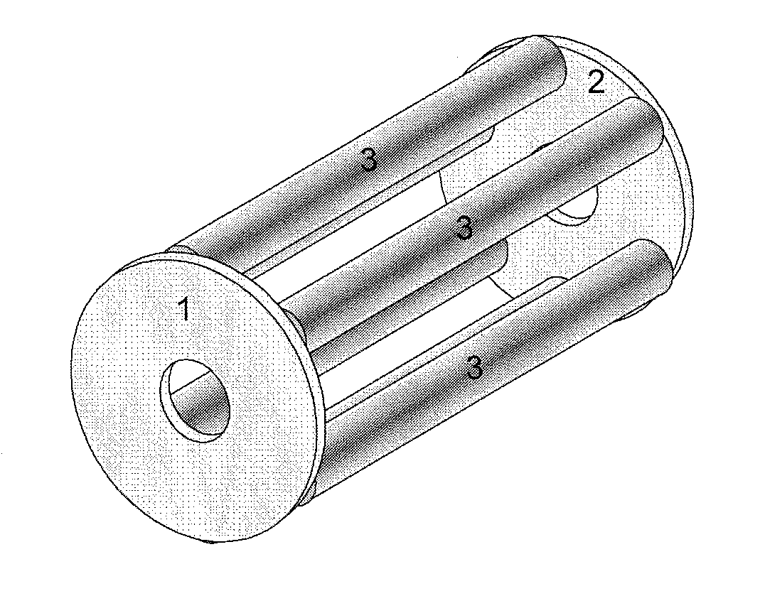
[0039]A linear RF ion trap with at least three pairs of rods, for example a hexapole or octopole ion trap, applies a new type of electronic power configuration in order to achieve a higher yield of fragment ions for a fragmentation by electron transfer (ETD). Rod systems with only quite small inside diameters of around three to five millimeters are used for the reaction cell. This means that only moderately high RF voltages of only a few hundred volts are required, and these can be generated in relatively simple and small pot core transformers, so the price of the configuration is kept within reasonable limits.

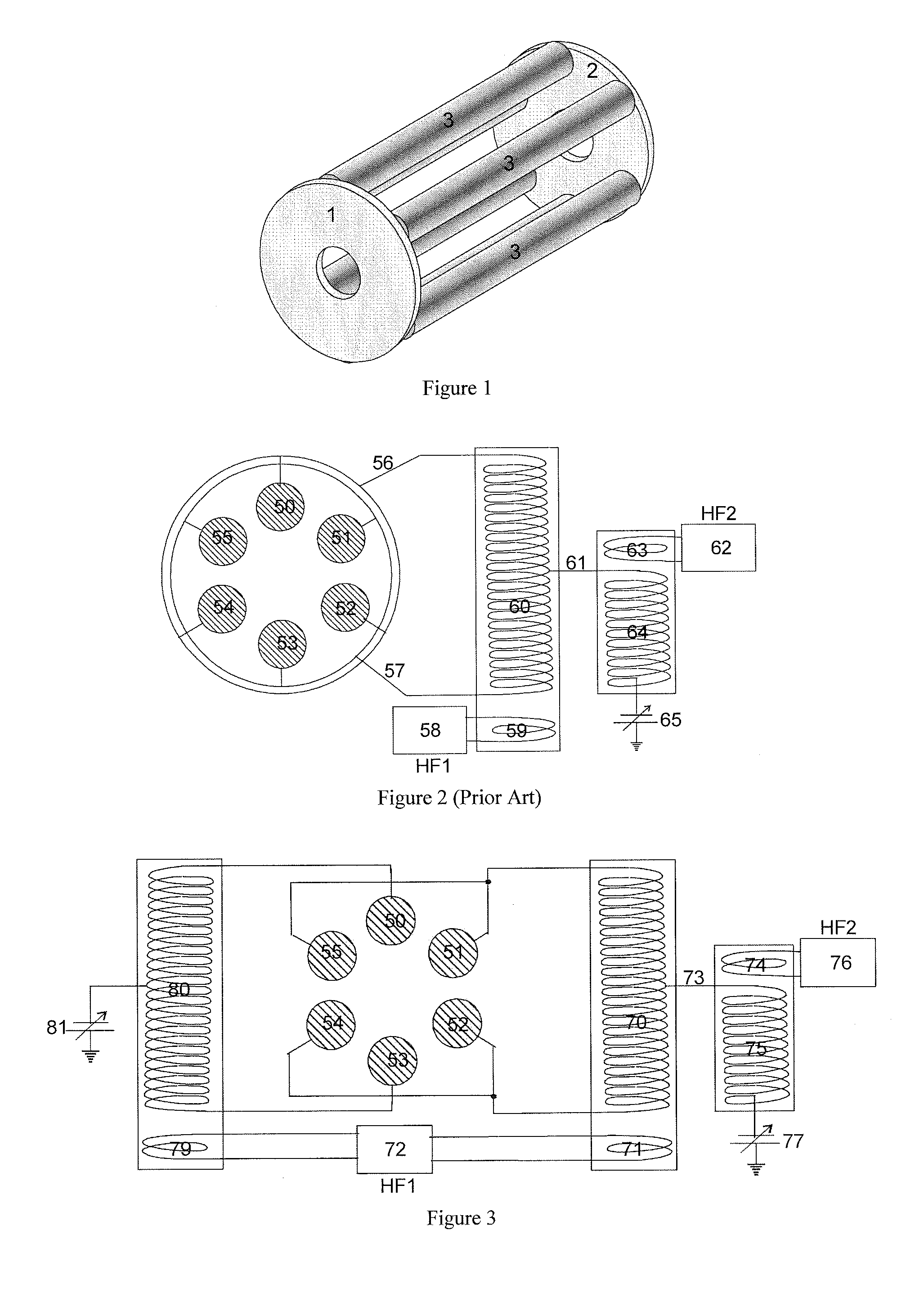
[0040]FIG. 3 shows an embodiment for the wiring configuration of the pole rods 50 to 55 of a hexapole ion trap, where four supply leads and three RF transformers are now required, justified by the higher yield of fragment ions. A single-phase second RF voltage is used here, connected to four of the six rods. It may even still more effective for a high ETD yield to connect this...


PUM


Abstract

The invention relates to a linear multipole ion storage device which is suitable for reactions between positive and negative ions, and for fragmentation reactions by electron transfer dissociation (ETD) in particular. The invention uses a linear RF ion trap with at least three pairs of rods with a new type of electronic power supply. The two phases of a first RF voltage are applied to the pole rods alternately around the circumference and confine positive as well as negative ions in the radial direction. A second RF voltage is either applied single-phase to some of the pole rods, but not to all of them, or two-phase to unequal numbers of pole rods so that the axis potential oscillates with the frequency of this second RF voltage and generates a pseudopotential barrier which acts axially on ions of both polarities at the ends of the ion storage device. In the interior, the second RF produces a complex superposition field resulting in an increased fragmentation yield for ETD.

Description

PRIORITY INFORMATION[0001]This patent application claims priority from German Patent Application 10 2010 022 184.8 filed on May 21, 2010, which is hereby incorporated by reference.FIELD OF THE INVENTION[0002]The invention relates to a linear multipole ion storage device which is suitable for reactions between positive and negative ions, and for fragmentation reactions by electron transfer dissociation (ETD).BACKGROUND OF THE INVENTION[0003]Where the term “mass” is used below it does not refer to the “physical mass” m, but to the “charge-related mass” m / z, where z is the number of the ion's uncompensated elementary charges. When simply “mass” or the “mass of the ions” is referred to here, it is always to be understood as the charge-related mass fraction m / z unless there is a note expressly stating otherwise. The terms “light ions” and “heavy ions” also relate to the charge-related mass fraction m / z.[0004]The investigation of the structures, characteristics and activities of proteins,...

Claims


Application Information

Patent Timeline
Patent Type & Authority Applications(United States)
IPC IPC(8): H01J49/02
CPCH01J49/063H01J49/0072H01J49/022H01J49/4225
Inventor STOERMER, CARSTENMICHELMANN, KARSTENSCHUBERT, MICHAEL
Owner BRUKER DALTONIK GMBH & CO KG
Why Eureka
Try Eureka