
Perceptive global positioning device and method thereof

a global positioning and global positioning technology, applied in measurement devices, satellite radio beaconing, instruments, etc., can solve the problems of reducing the accuracy of navigation, difficulty in establishing reception rules, and affecting so as to improve the accuracy of positioning effect, increase the cost, and improve the effect of accuracy

Inactive Publication Date: 2011-11-24
JIUNG YAO HUANG +1
View PDF9 Cites 16 Cited by
  • Summary
  • Abstract
  • Description
  • Claims
  • Application Information

AI Technical Summary

Benefits of technology

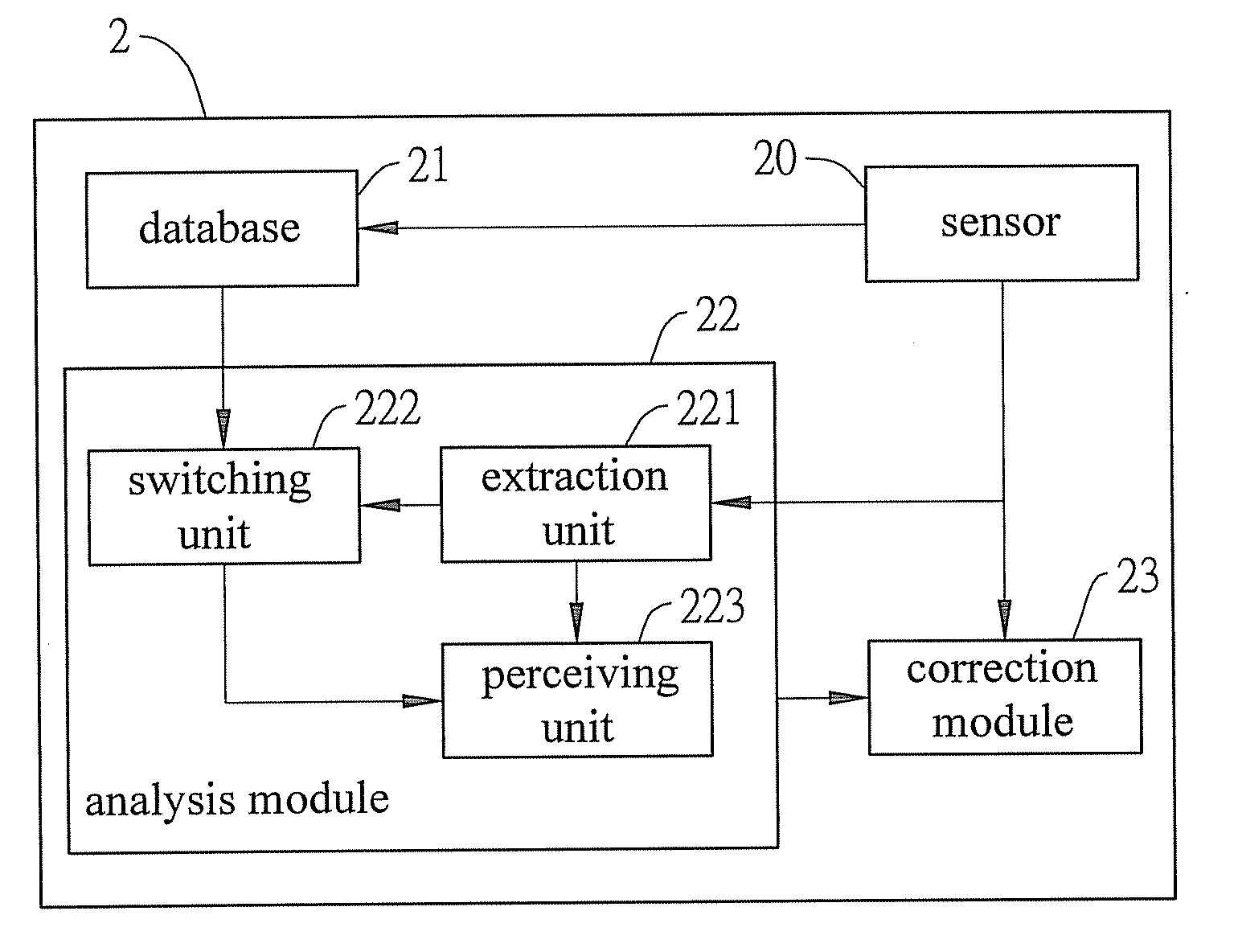
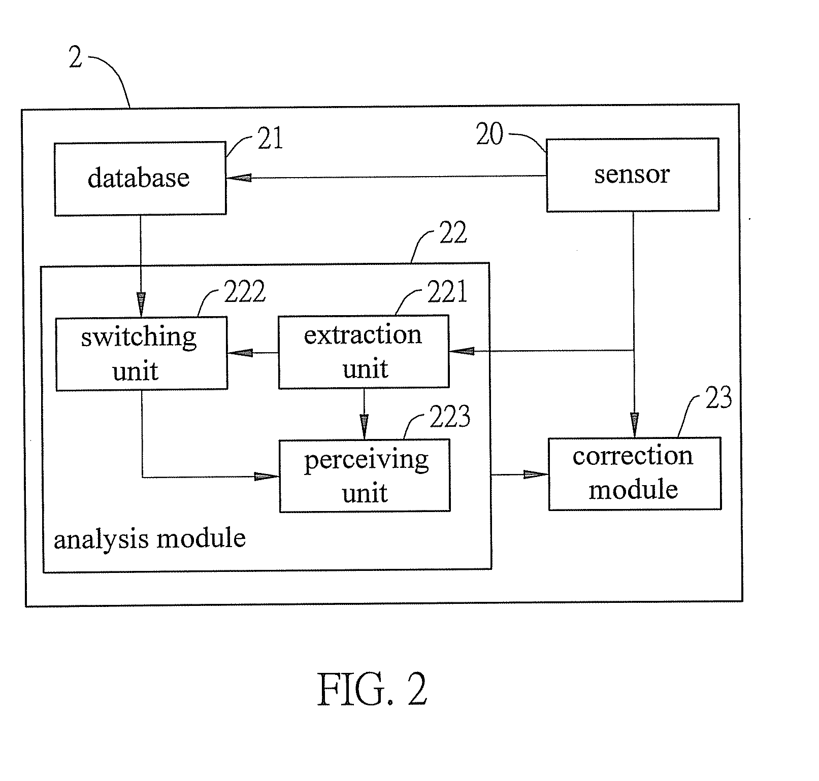
[0009]Compared with the prior art, the present invention provides a perceptive global positioning device that, after receiving positioning data transmitted from a satellite, calculates possible behavior states of the carrier through an optimal behavioral transition matrix, determines an error value between the currently received positioning data and possible behavior information, and corrects errors in the positioning data. By adding the sense data analysis of the carrier, the predictable behavior states of the carrier may be obtained and compared with the received data to determine errors. The errors may be corrected based on the comparison results and the accuracy of positioning effect may be improved accordingly. Hence, the problems of the conventional global positioning equipment may be addressed to overcome low accuracy because of environmental factors and equipment factors. Through the perceptive global positioning method of the present invention, only the feature data of the behavior states of a carrier are extracted, which avoids the problems of the prior art that adds navigation equipment, resulting in increased costs and introduced errors. In the present invention, the received positioning data are examined through the prediction of behavior states of a carrier, and the error conditions are also corrected. Therefore, the global positioning accuracy is greatly improved.

Problems solved by technology

Although various navigation techniques have been developed, these navigation techniques still suffer from certain defects.
For example, the landmark-based technique will cause navigation errors if landmarks are erroneously marked; the dead reckoning technique easily generates accumulative errors over time, resulting in its navigation accuracy being significantly diminished; the celestial navigation technique accomplishes positioning by viewing the location of celestial bodies, but a tiny measured error in the angle to a celestial body will result in a large positioning error because the measured carrier is always at a great distance from celestial bodies; the inertial navigation technique, which perceives the location of the carrier by measuring the second derivative of an inertial acceleration, also is subject to accumulative errors; and the radio navigation technique, which utilizes a fixed-point radio wave-emitting source to perform navigation, has difficulty in establishing reception rules to compensate for complicated errors attributed to radio wave transmission being easily affected by topography.
The GPS navigation system still contains errors with regard to positioning.
As for a GPS receiver, these aforesaid errors are inevitable.
However, the absolute technique has a disadvantage in that it demands costly infrastructure to be provided.
The auxiliary inertial navigation equipment is easily influenced by gravity and bring about accumulative errors.
However, the AGPS technique cannot improve the positioning accuracy.
These relative software navigation operation techniques have inherent limitation and have to be applied under certain conditions.
Accordingly, there is still no way to solve the positioning error problem.
Therefore, the current GPS navigation techniques heavily count on hardware support and ignore the contextual information of GPS data.

Method used


Image

  • Perceptive global positioning device and method thereof
  • Perceptive global positioning device and method thereof
  • Perceptive global positioning device and method thereof

Examples


Embodiment Construction

[0016]The following illustrative embodiments are provided to illustrate the disclosure of the present invention and advantages thereof, wherein these and other advantages and effects can be readily understood by those in the art after reading the disclosure of this specification. The present invention can also be performed or applied by other embodiments. The details of the specification are on the basis of particular points and applications, and numerous modifications and variations can be devised without departing from the spirit of the present invention.

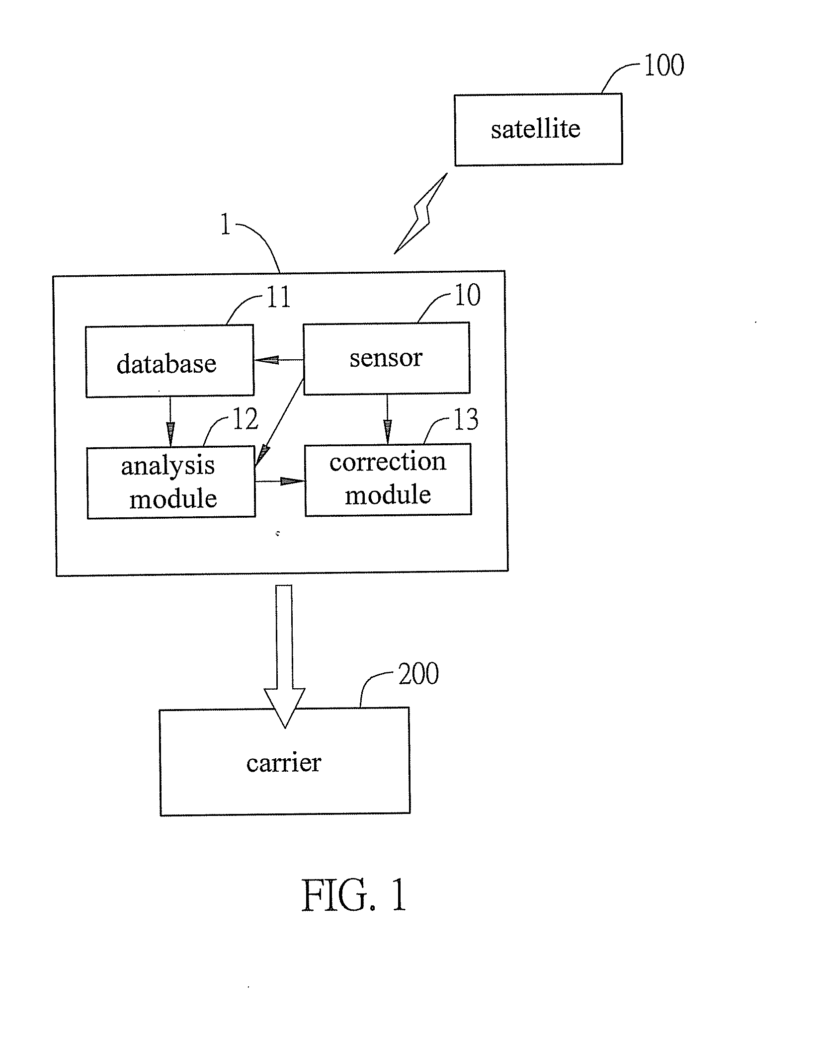
[0017]FIG. 1 is a functional block diagram of a perceptive global positioning device 1 according to the present invention. The perceptive global positioning device 1 receives positioning signals transmitted from satellites 100, using the signals to determine behavior states of a carrier 200 to thereby correct errors in the positioning data of the carrier 200. The perceptive global positioning device 1 comprises a sensor 10, a data...


PUM


Abstract

A perceptive global positioning device is disposed on or carried by a carrier (vehicle, pedestrian, etc.) for receiving positioning signals transmitted from satellites, to detect various behavioral states related to movement and correct errors in positioning data for positioning the carrier. The positioning device includes a sensor for receiving positioning data related to the global position of the carrier transmitted from satellites, a database for storing the positioning data received by the sensor and a preset behavioral transition matrix of the carrier, an analysis module for analyzing the positioning data and behavioral transition matrix to obtain predictable behavior data, and a correction module for comparing the predictable behavior data with the positioning data so as to correct errors of the positioning data of the carrier, thereby overcoming the defect of inaccurate data as encountered in the prior art.

Description

BACKGROUND OF THE INVENTION[0001]1. Field of the Invention[0002]This invention relates to a perceptive global positioning device and method thereof, and more particularly, to a perceptive global positioning device for more accurately positioning the position of a carrier, such as a vehicle or pedestrian, and method thereof.[0003]2. Description of Related Art[0004]Conventional navigation technique can establish the approximate position of a carrier. Although various navigation techniques have been developed, these navigation techniques still suffer from certain defects. For example, the landmark-based technique will cause navigation errors if landmarks are erroneously marked; the dead reckoning technique easily generates accumulative errors over time, resulting in its navigation accuracy being significantly diminished; the celestial navigation technique accomplishes positioning by viewing the location of celestial bodies, but a tiny measured error in the angle to a celestial body wil...

Claims


Application Information

Patent Timeline
IPC IPC(8): G01S19/40
CPCG01S19/40
Inventor HUANG, JIUNG-YAOTSAI, CHUNG-HSIEN
Owner JIUNG YAO HUANG
Learn More