Antenna

Inactive Publication Date: 2011-11-24
QUALCOMM TECH INT
View PDF4 Cites 13 Cited by
  • Summary
  • Abstract
  • Description
  • Claims
  • Application Information

AI Technical Summary

Benefits of technology

The antenna of the present invention offers a significant increase in the bandwidth of the antenna, due to the use of two antenna elements of different lengths. This increased bandwidth reduces the antenna's susceptibility to manufacturing tolerances of impedance matching inductors and capacitors, as the antenna

Problems solved by technology

However, resistors are lossy components, and the use of resistors to match the antenna resistance to that of the circuit to which the antenna is connected can give rise to losses of 10*log(4/46)=10 dB (where “log” is the b

Method used


Image

  • Antenna
  • Antenna
  • Antenna

Examples


Example

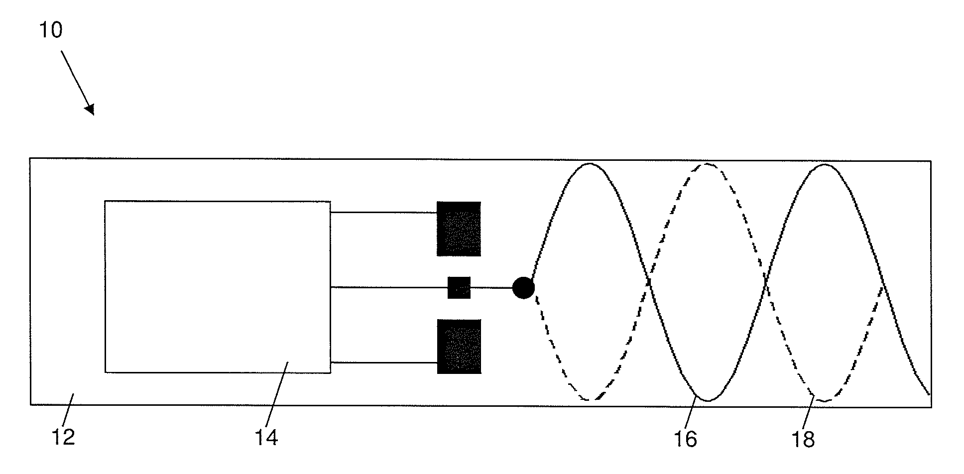
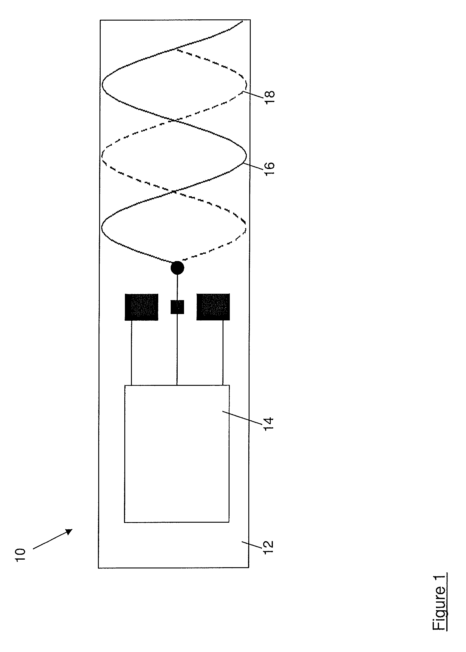
Referring first to FIG. 1, a wireless subsystem module for use in a device such as a mobile telephone or a laptop computer is shown generally at 10. The wireless subsystem module 10 is mounted on a substrate 12 of a material such as fibreglass, for example FR4, which supports a plurality (for example four) of circuit layers, one of which is at ground or 0 volts potential and is referred to as a “ground plane”.

One or more integrated circuits 14 containing transmit and receive circuits is mounted on the substrate 12 and is connected by tracks printed or otherwise provided on the layers of the substrate 12 to a number of discrete components such as filters, resistors, capacitors and inductors which perform functions such as impedance matching of the transmit and receive circuits to an antenna of the wireless subsystem module 10. The structure and operation of these components will not be described in detail here, since they are not the focus of the present invention.

The wireless subsys...


PUM


Abstract

An antenna comprising a substrate (12) having on a first side a first antenna element (16, 32) and on a second side a second antenna element (18, 34) which is of a different length to the first antenna element (16,32).

Description

TECHNICAL FIELDThe present invention relates to an antenna, and in particular to an antenna suitable for use in radio systems such as Bluetooth® and Wi-Fi® which use the 2.4 GHz frequency band, to a wireless subsystem module including such an antenna, and to a device such as a mobile telephone or laptop computer including such an antenna.BACKGROUND TO THE INVENTIONMany portable devices such as laptop computers, mobile telephones and the like include wireless subsystems such as Bluetooth® and Wi-Fi®. Typically manufacturers of such portable devices require modules implementing wireless subsystems which are less than a quarter of a wavelength long for an operating frequency of 2.45 GHz. For an efficient antenna system, a length of half of the operating wavelength would be preferred. A further requirement is that these modules must be low-cost, which precludes the use of expensive ceramic materials in the antennas of the wireless subsystems.It is commonplace to use printed antennas in ...

Claims


Application Information

Patent Timeline
IPC IPC(8): H01Q21/00H01Q5/371
CPCH01Q1/242H01Q1/36H01Q5/371H01Q21/30H01Q1/38
Inventor SMITH, LESLIE DAVID
Owner QUALCOMM TECH INT
Why Eureka
Try Eureka