
Wireless temperature sensing and control system for metal kiln and method of using the same

a control system and temperature sensing technology, applied in the field of metal furnaces or kilns, can solve the problems of high temperature excursion, manual intervention, and inability to monitor the temperature of traditional rotary aluminum kilns, and achieve the effects of reducing the number of kilns, and improving the efficiency of kilns

Active Publication Date: 2011-11-24
GILLESPIE & POWERS INC
View PDF3 Cites 8 Cited by
  • Summary
  • Abstract
  • Description
  • Claims
  • Application Information

AI Technical Summary

Problems solved by technology

Due to the difficulties in accessing the rotating material during operation, the temperatures in traditional rotary aluminum kilns are not regularly monitored.
This requires manual intervention and is not particularly accurate.
Unfortunately, failure to consistently and accurately monitor the conditions in the kiln can lead to fires.
These fires result when the feed material reaches the volatilization point too rapidly and the feed material begins to rapidly oxidize and generate its own heat, leading to a high temperature excursion (i.e. “overtemp event”).
A fire in a rotary aluminum kiln can require a costly shut-down, will likely destroy the feed material, and can damage the kiln and other associated equipment.
Oxidation of these particles in the kiln occurs very rapidly, resulting in highly combustible partially oxidized aluminum and magnesium.
However, once ignition occurs the fire can flash rapidly throughout the kiln.

Method used


Image

  • Wireless temperature sensing and control system for metal kiln and method of using the same
  • Wireless temperature sensing and control system for metal kiln and method of using the same

Examples


Embodiment Construction

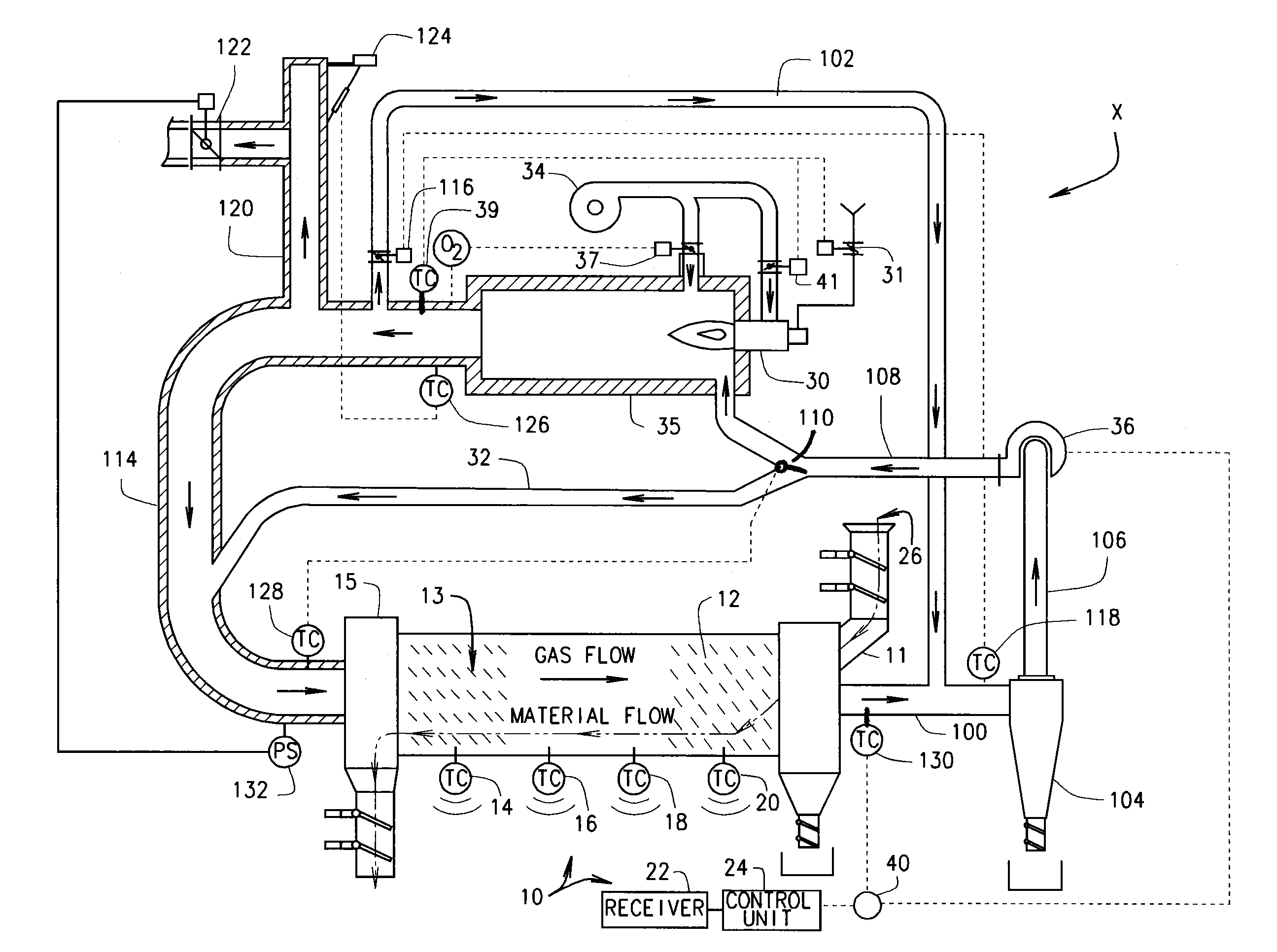
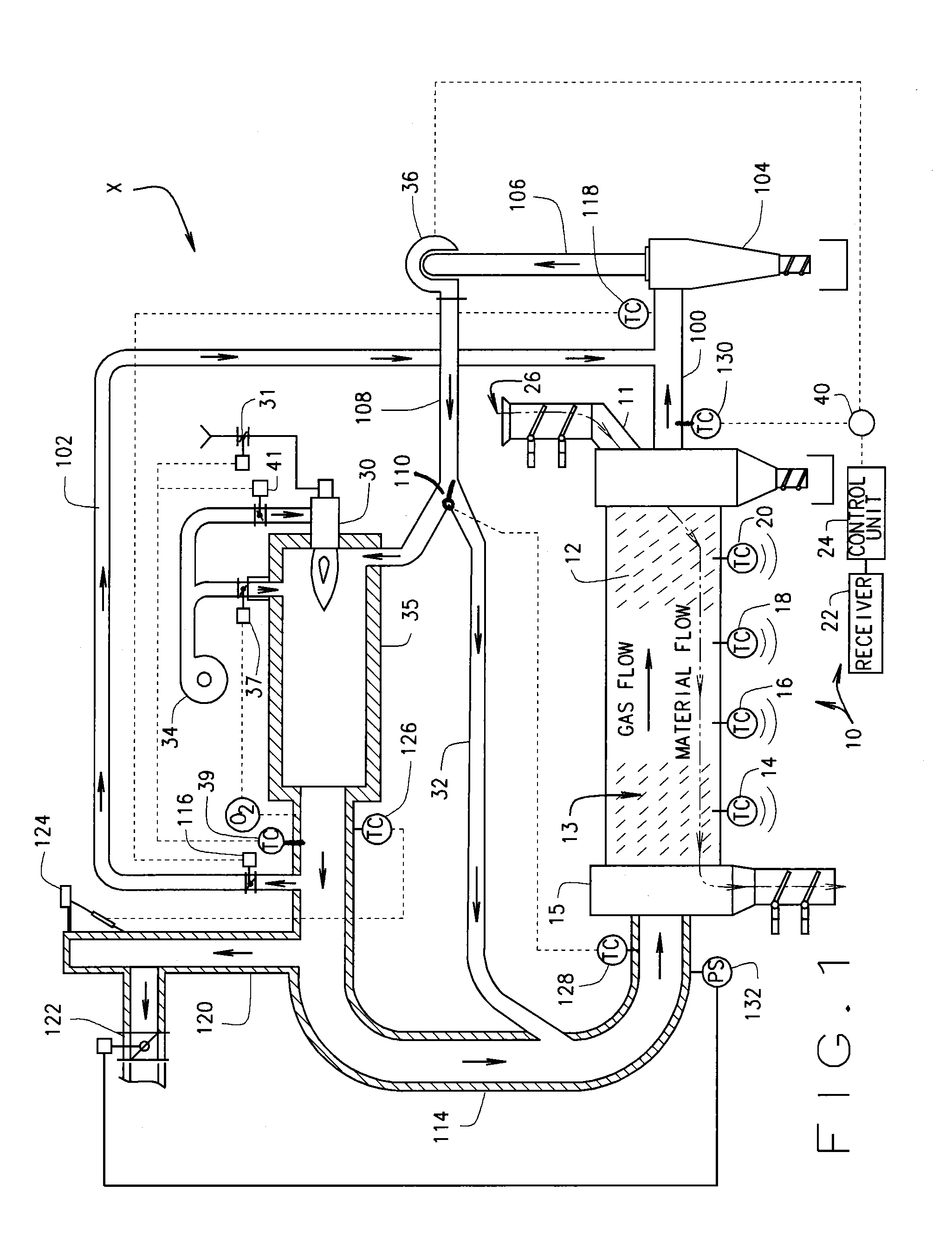
[0011]In referring to the drawings, a schematic embodiment of the novel wireless temperature sensing and control system for metal kiln 10 of the present invention is shown generally in FIG. 1, where the present invention is depicted by way of example as integrated into a representative mass flow delacquering system X with a rotary aluminum kiln 12 having a delacquering zone 13 within the kiln 12. As can be seen, a set of four independent high temperature thermocouples 14, 16, 18 and 20, are positioned along the length of the kiln 12. In practice, the thermocouples 14, 16, 18 and 20 are positioned with at least the temperature sensing portion of the thermocouple exposed to the delacquering zone 13 within the rotary kiln 12. All of the thermocouples 14, 16, 18 and 20 are configured to detect temperature readings in the kiln 12, including temperature readings in excess of the melting point of aluminum, and are further configured to transmit the temperature readings they sense inside of...


PUM


Abstract

A rotary aluminum kiln temperature regulation system comprising a temperature sensing device in the kiln that is configured to take temperature readings in an area of the kiln in proximity to the temperature sensing device. The system including a wireless transmitter operatively associated with the temperature sensing device and a receiver wirelessly associated with the transmitter, such that the transmitter and receiver wirelessly transmit the temperature readings taken by the temperature sensing device from the transmitter to the receiver. The system also including a control unit operatively connected to the receiver that is configured to receive the transmitted temperature readings and determine when the transmitted temperature readings exceed a predefined temperature setpoint. The control unit is operatively connected to a heat flow control device that can adjust heat flow inside the kiln in proximity to the temperature sensing device, such that the control unit regulates the heat flow control device to maintain a desired level of heat flow in the kiln in proximity to the temperature sensing device in response to the temperature readings transmitted from the temperature sensing device.

Description

CROSS REFERENCE TO RELATED APPLICATIONS[0001]This application derives and claims priority from U.S. provisional application 61 / 346,199 filed 19 May 2010, which application is incorporated herein by reference.STATEMENT REGARDING FEDERALLY SPONSORED RESEARCH OR DEVELOPMENT[0002]Not applicable.BACKGROUND OF THE INVENTION[0003]This invention relates principally to a metal furnace or kiln, and more particularly to a temperature sensing and control system for rotary aluminum delacquering kilns using wireless thermocouples or comparable temperature sensing devices.[0004]It has for some time been a standard practice to recycle scrap metals, and in particular scrap aluminum. Various furnace and kiln systems exist that are designed to recycle and recover aluminum from various sources of scrap, such as used beverage cans (“UBC”), siding, windows and door frames, etc. One of the first steps in these processes is to use a rotary kiln to remove the paints, oils, and other surface materials on the...

Claims


Application Information

Patent Timeline
IPC IPC(8): F27D19/00
CPCF27D19/00F27B7/42
Inventor PETERMAN, JOHN M.ROBERTS, MARK A.
Owner GILLESPIE & POWERS INC
Learn More