
Detachable sports goal net device and system

Inactive Publication Date: 2011-11-24
LYNCH PETER G
View PDF11 Cites 18 Cited by
  • Summary
  • Abstract
  • Description
  • Claims
  • Application Information

AI Technical Summary

Benefits of technology

[0013]The seating portions may further facilitate installation of the removable net component on the goal structure.
[0021]According to a preferred embodiment, the netting component may include a drawstring mechanism to draw the netting rearward of the goal front to provide tension on the netting. Preferably, the drawstring mechanism may be provided at the net seams. The drawstring mechanism is designed to improve and enhance playability using the net system.

Problems solved by technology

However, in many cases the sports are played outdoors and, as a result, the goal and netting are exposed to the elements.
Sports goal frames and nets are generally cumbersome to take indoors and are left out in the open.
As a result, the components including the netting often are prone to damage, including not only by the elements such as weather conditions, but also animals, vandalism and even theft.
One of the most common ways to secure netting to a goal structure is by threading a nylon string through the net to the post, which is a time-consuming effort and needs continuous care and adjustments in order to keep the net secure to the frame system without gaps and holes.
Though a net may be removed from the structure, it is generally difficult to reattach the net, especially if a plurality of clips or fastening elements need to be installed.
The prior nets are often not only prone to breakage, but also are difficult to remove when they are to be replaced.
Though some have attempted solutions involving the use of nets which are claimed to be designed for easy replacement, often the netting is held in a manner that the netting or other structures holding the netting may interfere with the goal and the playability of the game with such goals.

Method used


Image

  • Detachable sports goal net device and system
  • Detachable sports goal net device and system
  • Detachable sports goal net device and system

Examples


Embodiment Construction

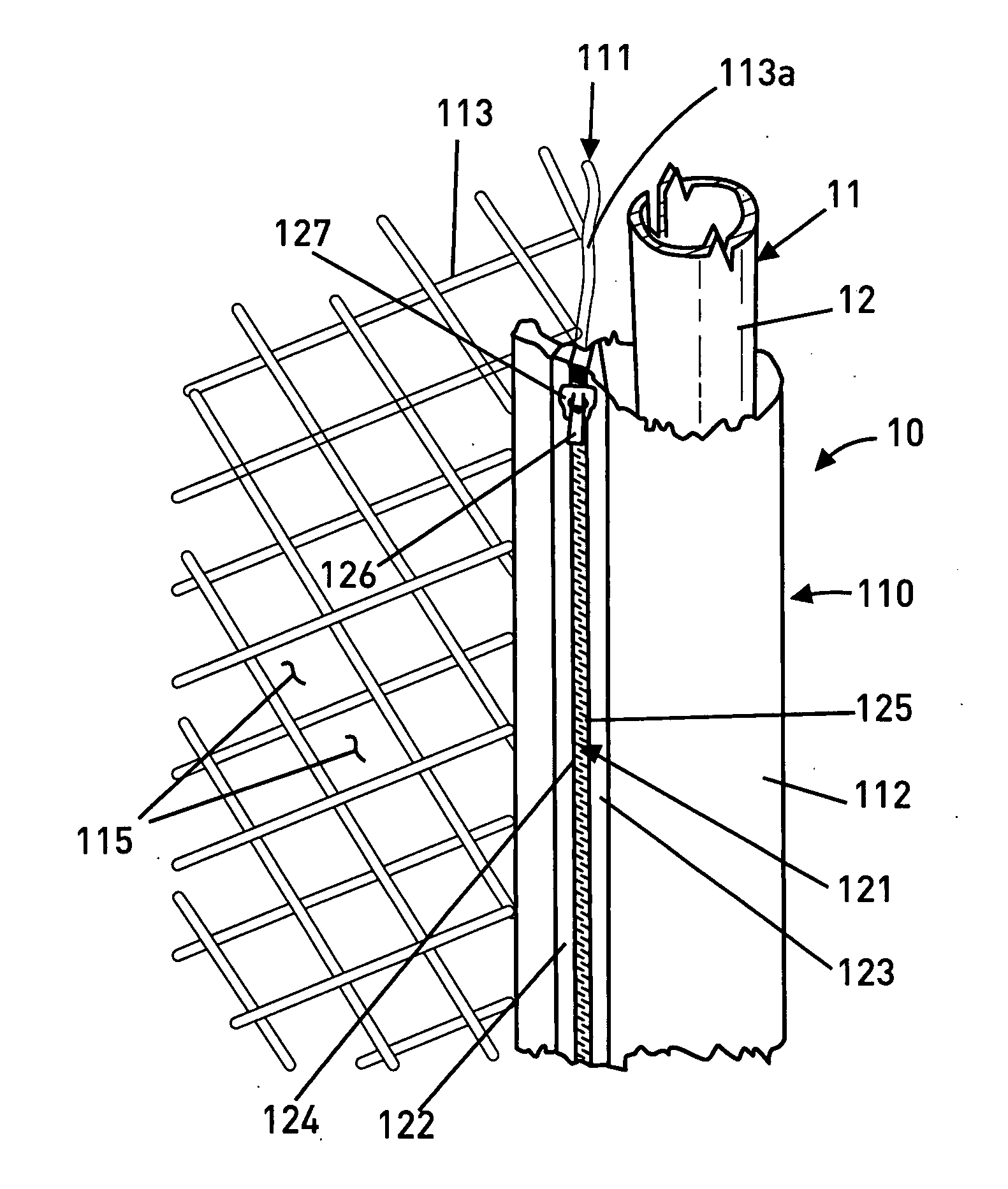
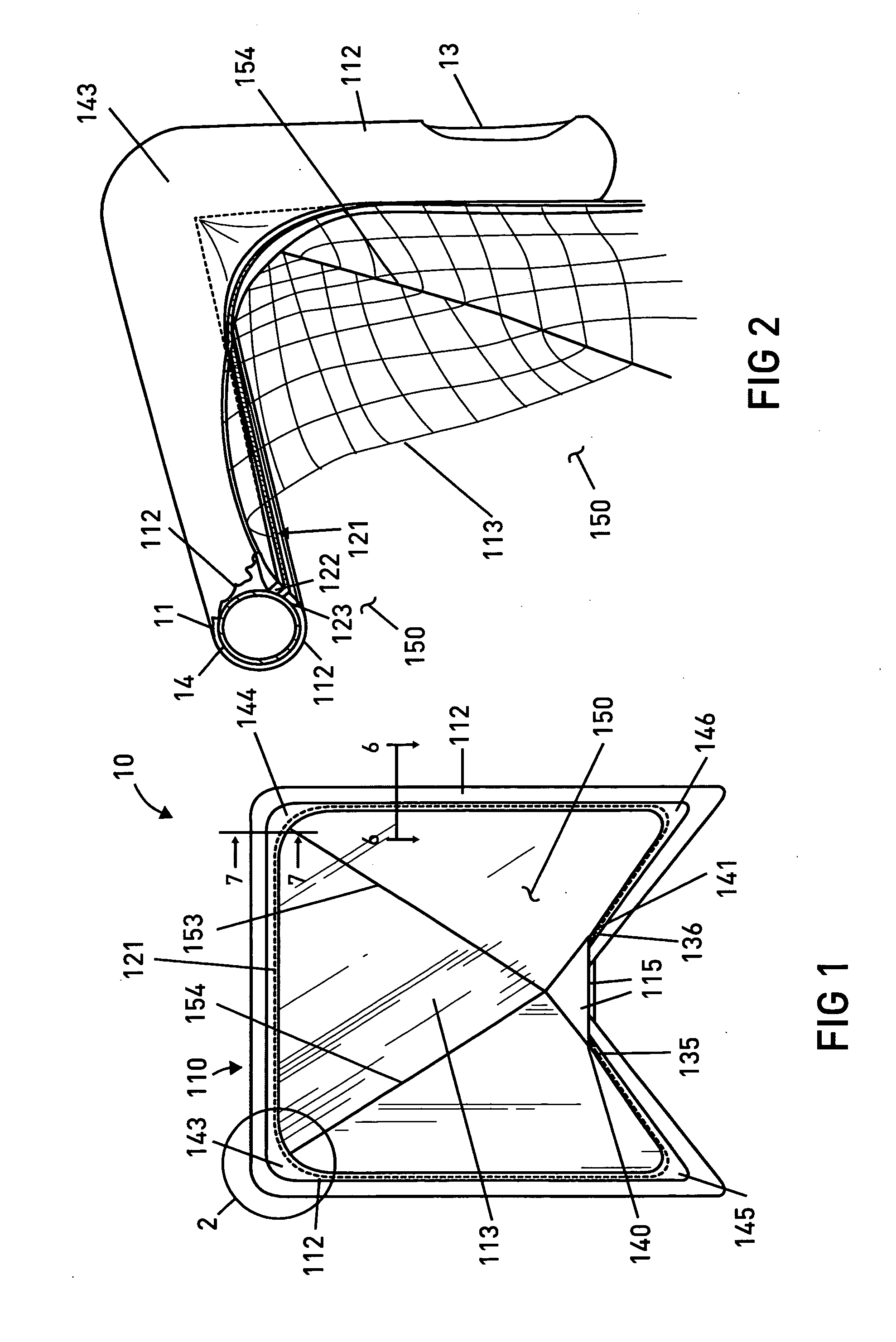
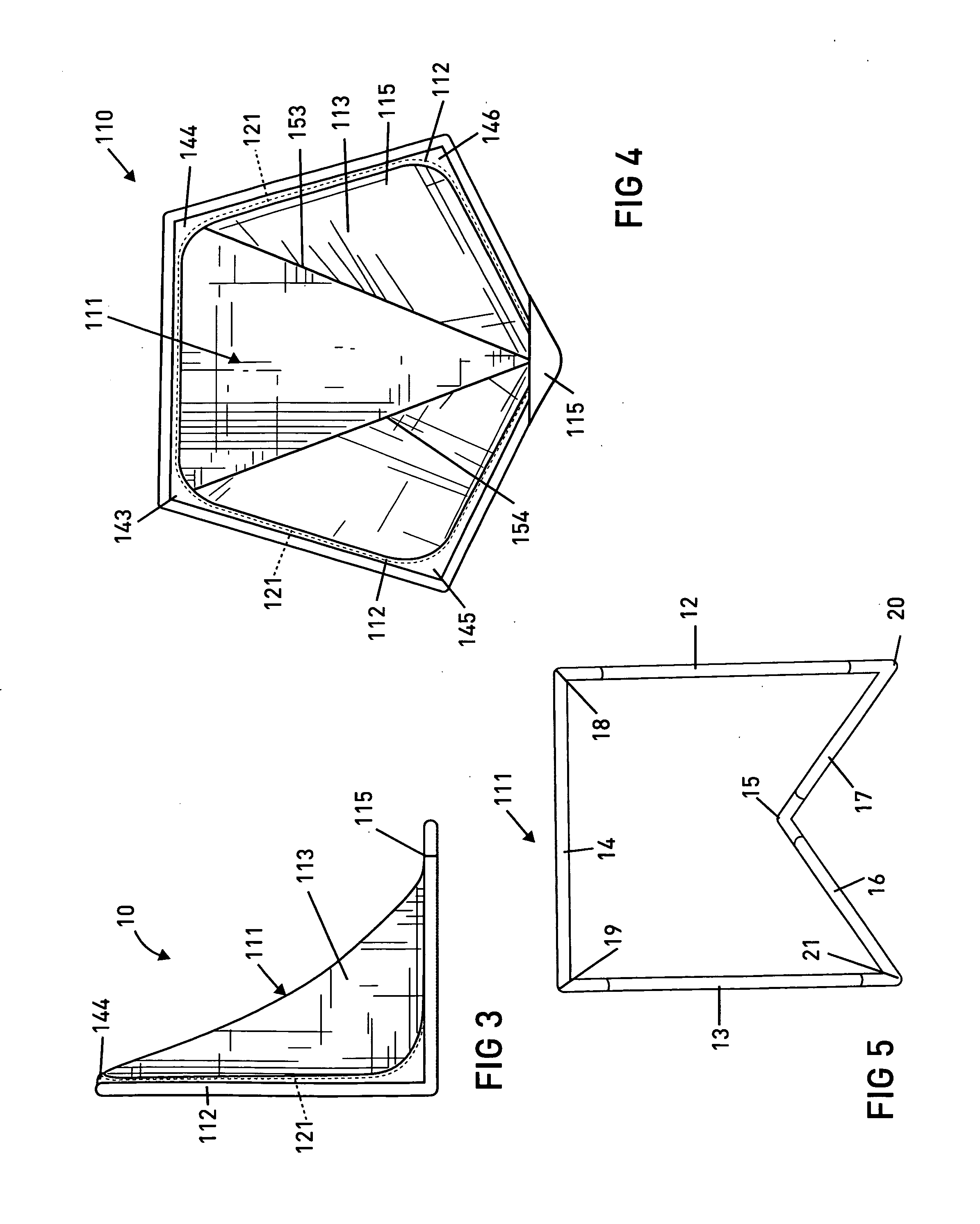
[0045]Referring to FIG. 1, there is illustrated a preferred embodiment of a sports goal system 10. The sports goal system 10 is shown including a netting assembly 110 installed on a goal frame structure 11 (FIG. 5). The sports goal system 10 is illustrated configured as a lacrosse goal, which is shown in a preferred configuration in FIG. 4 having a front frame portion including a right side post 12, a left side post 13 and a cross bar 14 with a bottom frame portion including a left base section 16, a right base section 17 and a rear structure 15 connecting the base sections 16, 17. The rear structure 15 may be a frame portion or other element that connects with the right base section 17 and the left base section 16. Preferably, the rear structure 15 provides stability at the rear of the goal. According to a preferred exemplary goal frame structure 11, the front posts 12, 13 and cross bar 14 preferably connect with each other to form the front frame portion. The goal frame structure ...


PUM

PropertyMeasurementUnit
Timeaaaaaaaaaa
Lengthaaaaaaaaaa
Coloraaaaaaaaaa

Abstract

A sports goal net system including a removable net component that may be installed and removed quickly and easily by one person from the goal structure or frame as desired, where netting is provided with an attachment component having a zipper that facilitates the connection of the removable net component to a goal structure, such as the frame or posts of a sports goal, the net component being attachable by moving the slider of a zipper along the edge of the attachment component to secure the attachment component to itself so that the attachment component surrounds the goal structure to secure the net assembly to the goal.

Description

BACKGROUND OF THE INVENTION[0001]1. Field of the Invention[0002]The present invention relates to the field of sports goal nets, such as, for example those used for lacrosse, hockey and soccer, and more particularly to a sports goal net system having a removably provided net that is easy to attach and remove.[0003]2. Brief Description of the Related Art[0004]Sports goals are widely used in connection with a number of sports, including, in particular, lacrosse, soccer and hockey. Sports goals routinely are constructed using a frame, which may be wood or metal, with netting held on the frame. Generally, the netting openings are sized so that the sport object, such as a ball or puck, will remain contained when it is forced against the netting, such as when a player makes a shot. However, in many cases the sports are played outdoors and, as a result, the goal and netting are exposed to the elements. Sports goal frames and nets are generally cumbersome to take indoors and are left out in ...

Claims


Application Information

Patent Timeline
IPC IPC(8): A63B63/00B23P11/00
CPCA63B63/004A63B2063/005Y10T29/49826A63B2243/005A63B2210/50A63B2102/14
Inventor LYNCH, PETER G.
Owner LYNCH PETER G
Learn More