Control device with an accelerometer system

a technology of accelerometer and control device, which is applied in the direction of acceleration measurement, acceleration measurement in multiple dimensions, and acceleration measurement using interia forces, etc. it can solve the problems of drift inaccuracy of velocity, distance traveled, orientation, angular velocity and orientation, and inaccuracy of velocity reporting, so as to reduce the vibration of movement

Active Publication Date: 2011-11-24
LOGITECH EURO SA
View PDF2 Cites 55 Cited by
  • Summary
  • Abstract
  • Description
  • Claims
  • Application Information

AI Technical Summary

Benefits of technology

[0016]In one embodiment, movement vibration is reduced using a mechanical filter or damper inside the pointing device o...

Problems solved by technology

Drift includes the inaccurate reporting of velocity, distance traveled, location, angular velocity, and orientation over time.
Drift inaccuracies for velocity occur from errors in the measurement of acceleration and the integration of acceleration to calculate the velocity.
A traditional 3D mouse, such as the traditional mice descri...

Method used


Image

  • Control device with an accelerometer system
  • Control device with an accelerometer system
  • Control device with an accelerometer system

Examples


Embodiment Construction

[0031]The present invention provides a position detection system for a pointing device using microelectromechanical systems (MEMS) technology. In an embodiment, two-dimensional movement is detected, with an accelerometer in the z direction being used to detect lift-off of the pointing device to stop cursor movement.

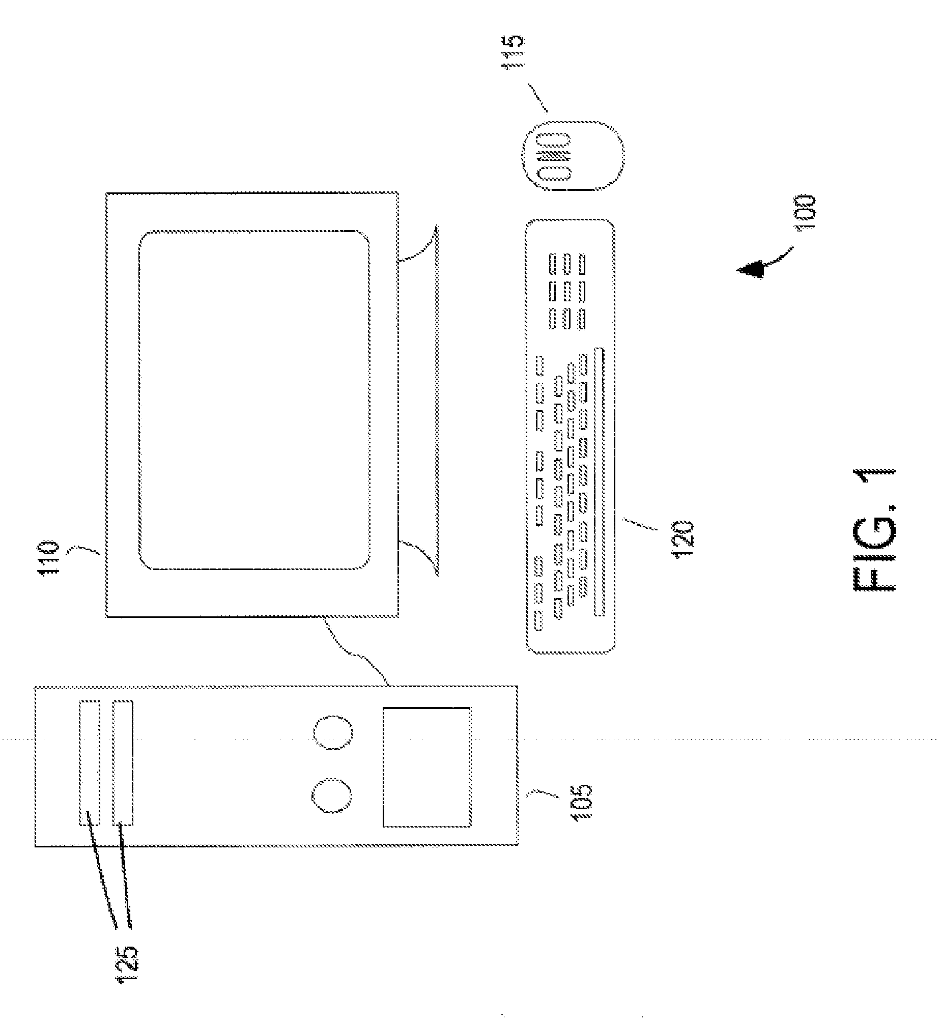
[0032]FIG. 1 is a simplified schematic of a computer system 100 according to one embodiment of the present invention. Computer system 100 includes a computer 105, a monitor 110, and a control device 115, such as a mouse, a puck, or the like. For convenience, the control device is referred to as a mouse herein, but it is to be understood the embodiments of the present invention are not limited to mice, and may include other devices, such as, but not limited to, remote controls, etc. The computer system may also include a keyboard 120 or the like. For computer system 100, the mouse and the keyboard are configured to control various aspects of computer 105 and monitor 110. F...


PUM


Abstract

A control device includes a two-dimensional inertial system configured to measure an acceleration of the control device. A control circuit is coupled to the two-dimensional inertial system where the control circuit is configured to receive acceleration information for the acceleration measured by the two-dimensional inertial system. The control circuit is further configured to integrate the acceleration information to calculate the velocity of the control device and determine if the velocity of the control device becomes zero along one or both of the two dimensions for which the two-dimensional inertial system is configured to measure acceleration. The control circuit is further configured to correct a drift in the velocity if the control circuit determines that the velocity is zero along one or both of the two dimensions.

Description

CROSS-REFERENCES TO RELATED APPLICATIONS[0001]The present application claims benefit under 35 U.S.C. §119(e) of U.S. Provisional Patent Application No. 61 / 346,389, filed on May 19, 2010, and entitled “Control Device with an Accelerometer System.” The present application is related to co-pending U.S. patent application Ser. No. 12 / 130,883, filed on May 30, 2008, entitled “Pointing Device with Improved Cursor Control In-Air and Allowing Multiple Modes of Operations” and U.S. patent application Ser. No. 12 / 030,813, filed Feb. 13, 2008, entitled “Pen Mouse.” U.S. Provisional Patent Application No. 61 / 346,389 and U.S. patent application Ser. Nos. 12 / 130,883 and 12 / 030,813 are hereby incorporated by reference in their entirety for all purposes.BACKGROUND OF THE INVENTION[0002]The present invention relates to control devices. More particularly, the present invention relates to computer mice having accelerometers to detect motion.[0003]Inertial systems are used in a number of devices such a...

Claims


Application Information

Patent Timeline
IPC IPC(8): G06F19/00G01P15/18G06F3/038
CPCG01P7/00G01P15/18G06F3/038G06F3/03543G06F3/0346
Inventor DEJNABADI, HOOMANAMINIAN, KAMIARCHAUVIN, NICOLAS
Owner LOGITECH EURO SA
Why Eureka
Try Eureka