Method and device for flexible error correction encoding and corresponding computer program

a technology of error correction and encoding, applied in the field of error correction codes, can solve the problems of more difficult to deal with the problem of optimizing error correction codes, the minimum distance dsub>min /sub>is not optimal for these lengths n and k, etc., and achieve the effect of reducing complexity

Active Publication Date: 2011-11-24
3G LICENSING SA
View PDF2 Cites 7 Cited by
  • Summary
  • Abstract
  • Description
  • Claims
  • Application Information

AI Technical Summary

Benefits of technology

[0064]Thus, the choice of the different scrambling modules gives an optimum code of reduced complexity, both when encoding and when decoding.
[0065]The use of superimposed scrambling sub-modules of different types gives a great diversity of basic codes. Indeed, the permutations at input and / or at output of the basic codes give codes with different combinations of symbols. The increase in the diversity of the basic codes increases the minimum distance between two words of the resulting total code.

Problems solved by technology

These transmission errors are caused for example by the thermal noise of the electronic components of the receiver, electromagnetic scrambling (whether intentional or otherwise), echoes or multiple propagation in the case of wireless propagation or in an electrical energy network etc.
In general, one drawback of error correction codes having a length n and containing k payload information symbols lies in the fact that the minimum distance dmin is not optimal for these lengths n and k, i.e. the minimum distance is not the closest possible distance from an upper boundary for which the code enables the detection of the maximum number of errors.
Paradoxically, these problems of optimizing error correction codes are more difficult to deal with when the lengths n of the codes range from small to average, i.e. of the order of n<1000.

Method used


Image

  • Method and device for flexible error correction encoding and corresponding computer program
  • Method and device for flexible error correction encoding and corresponding computer program
  • Method and device for flexible error correction encoding and corresponding computer program

Examples


first embodiment

3. Description of a First Embodiment

[0152]Referring now to FIGS. 3a and 3b, we present a first embodiment of the encoding device according to the invention.

[0153]FIG. 3a illustrates the structure of an encoder according to an embodiment of the invention taking pieces of source data (x0, x1, x2 . . . x11) at input and delivering pieces of redundancy data (r0, r1, r2 . . . r11) at output.

[0154]These pieces of redundancy data can then be used, in combination with the source data, to form a code word.

[0155]The encoder thus made has three encoding stages cA, cB and cC, and two permutation stages π0. Each encoding stage has three basic encoding modules: (A0, A1, A2) for the first encoding stage cA, (B0, B1, B2) for the intermediate encoding stage cB and (C0, C1, C2) for the last encoding stage cC.

[0156]The numbers indicated at input and output of the permutation stages nO define the position of the symbols at input at a permutation stage and their corresponding position at output.

[0157]Ac...

second embodiment

4. Description of a Second Embodiment

[0165]Referring now to FIGS. 4a and 4b, we present a second embodiment of the encoding device according to the invention.

[0166]FIG. 4a illustrates an encoder according to an embodiment of the invention taking the pieces of data (x0, x1, x2 . . . x11 at input) and delivering the pieces of redundancy data (r0, r1, r2 r11) at output. Again, these pieces of redundant data can be used in combination with the source data to form a code word.

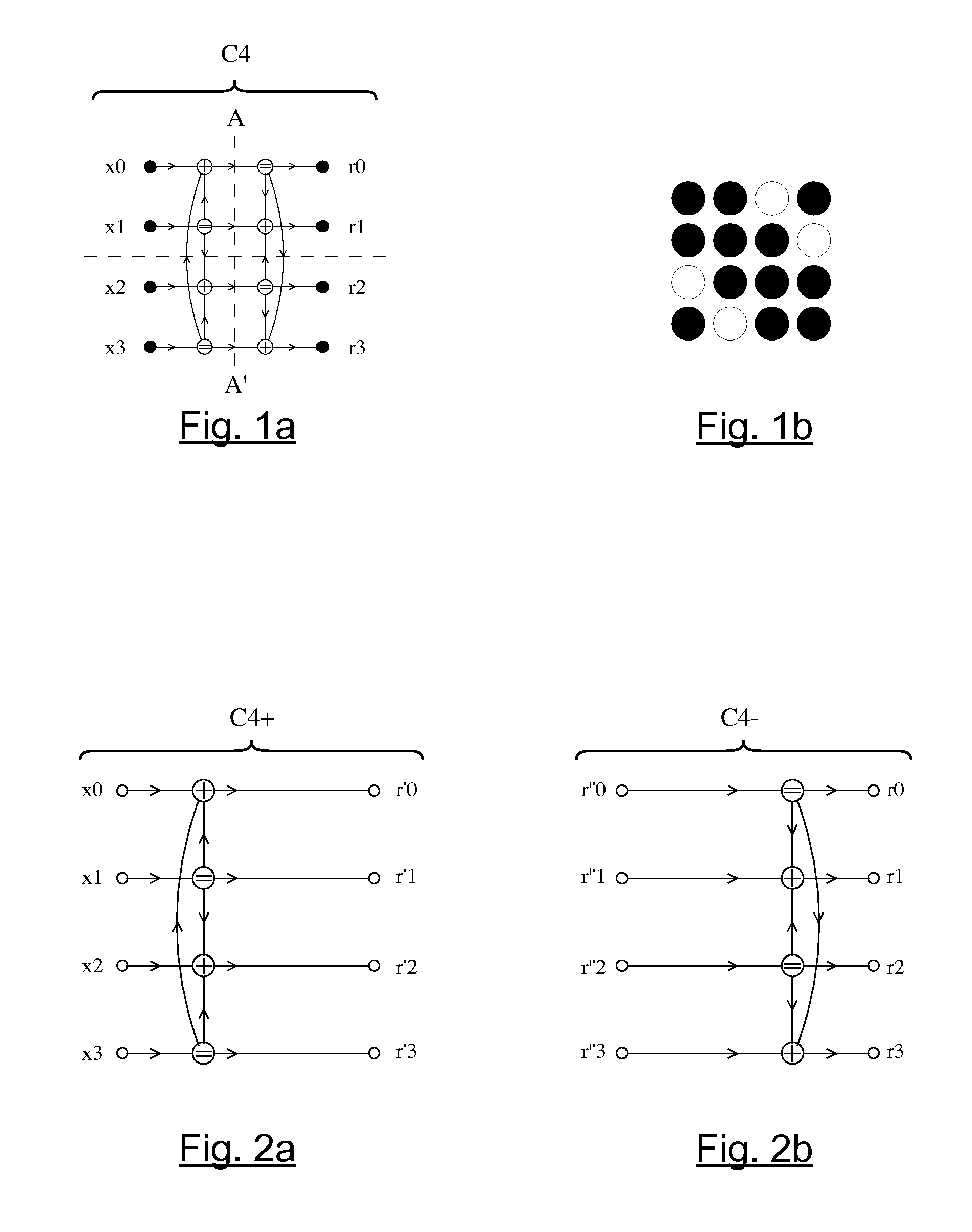
[0167]The encoder thus made includes three encoding stages cA, cB et cC, and two permutation stages π0. Each encoding stage has three basic encoding modules: the first encoding stage cA implements three Hamming left half-codes C4+ (A0, A1, A2), the intermediate encoding stage cB implements two compact Hamming codes C4 (B0, B2) and one identity code Id4, the last encoding stage cC implements three Hamming right half-codes C4− (C0, C1, C2).

[0168]As in the embodiment described here above, the permutations π0 used are 4...

third embodiment

5. Description of a Third Embodiment

[0179]Referring now to FIGS. 5a and 5b, we present a third embodiment of the encoding device according to the invention.

[0180]FIG. 5a illustrates an encoder of this kind according to an embodiment of the invention, taking the pieces of data (x0, x1, x2 . . . x15) at input and delivering the pieces of redundancy data (r0, r1, r2 . . . r15) at output.

[0181]The encoder thus made has three encoding stages cA, cB and cC, each comprising four basic encoding modules (A0, A1, A2, A3), (B0, B1, B2, B3) and (C0, C1, C2, C3), each implementing a compact Hamming code C4, and two permutation stages π0.

[0182]This encoder implements the same 4-cyclic type permutation pattern π0 as the one described in the first embodiment, i.e. a 4-cyclic type permutation with a parameter Δ=1.

[0183]The length of this code is equal to 32, i.e. 4 / 3 of the length of “simplified” Cortex-Golay code C1(24, 12, 8) described here above, and the minimum distance dmin of this code is iden...


PUM


Abstract

An error correction encoding device is provided that combines redundancy data with source data, said device including: at least three encoding stages and at least two permutation stages. Each encoding stage implements at least one set of three basic encoding modules, in which a first encoding stage receives said source data and a last encoding stage provides said redundancy data. Each encoding module implements a basic code and includes c inputs and c outputs, c being an integer. The permutation stages are inserted between two consecutive encoding stages and each permutation stage implements a c-cyclic permutation.

Description

CROSS-REFERENCE TO RELATED APPLICATIONS[0001]This Application is a Section 371 National Stage Application of International Application No. PCT / FR2010 / 050158, filed Feb. 1, 2010 and published as WO 2010 / 086572 on Aug. 5, 2010, not in English.STATEMENT REGARDING FEDERALLY SPONSORED RESEARCH OR DEVELOPMENT[0002]None.THE NAMES OF PARTIES TO A JOINT RESEARCH AGREEMENT[0003]None.FIELD OF THE DISCLOSURE[0004]The field of the disclosure is that of the encoding of digital data. More specifically, the disclosure pertains to error correction codes.[0005]The disclosure can be applied especially but not exclusively to the encoding of source data organized in data blocks that are independent of one another and therefore have to be encoded and decoded block by block, as well as to the encoding of data streams (convolutive encoding).BACKGROUND OF THE DISCLOSURE[0006]There are many known encoding techniques enabling the correction of transmission errors.[0007]These error correction codes enable the ...

Claims


Application Information

Patent Timeline
Patent Type & Authority Applications(United States)
IPC IPC(8): H03M13/19
CPCH03M13/136H03M13/19H03M13/6561H03M13/2785H03M13/27
Inventor CARLACH, JEAN-CLAUDE
Owner 3G LICENSING SA
Why Eureka
Try Eureka