De-cocking mechanism for striker-fired semi-automatic pistols

a semi-automatic pistol and decocking mechanism technology, applied in the field of safety mechanisms, can solve problems such as potential danger and pistol vulnerability to mishaps

Active Publication Date: 2011-12-01
BERETTA USA CORP
View PDF5 Cites 44 Cited by
  • Summary
  • Abstract
  • Description
  • Claims
  • Application Information

AI Technical Summary

Benefits of technology

[0003]Striker-fired pistols have been well-developed by the art. Such pistols are absent a traditional hammer and firing pin. They employ a spring-biased striker pin urged into a “cocked” pre-firing condition by a cocking lever actuated by a trigger bar linked to a finger trigger. The striker pin itself is typically pre-cocked by the forward movement of the slide into battery position. The shooter's finger action on the trigger is relieved upon discharge by the striker pin detonating the explosive charge in the ammunition. This simplicity of both operation and design for striker pin fired guns, while making such guns inexpensive to manufacture, can make the pistol vulnerable to mishaps caused by accidental drops of the weapon or rough handling.
[0005]The new and improved cocking / de-cocking mechanism has a minimum number of parts and lends itself to manufacture using inexpensive, high volume techniques such as stamping and casting, rather than comparatively expensive machining processes, and utilizing off-the-shelf elements as well. The new trigger bar may be stamped at low cost while the cocking lever may be made at low cost by metal injection molding.
[0006]The present invention eliminates this danger attendant with trigger squeezing “dry firing” by providing a simple, safe, and very inexpensive cocking / de-cocking arrangement predicated upon the actions of a specially configured multiple tasking cocking lever, specially configured trigger bar, in cooperation with the slide, frame, and receiver. For a full understanding and appreciation of the new de-cocking mechanism, reference should be made to the following detailed description of the invention taken in conjunction with the accompanying drawings illustrating the mechanism and principles of the invention.

Problems solved by technology

The new and improved arrangement permits striker-fired pistols to be simply disassembled without having to pull the trigger, a potentially dangerous condition if ammunition is in the firing chamber, as is the case with earlier de-cocking systems.
This simplicity of both operation and design for striker pin fired guns, while making such guns inexpensive to manufacture, can make the pistol vulnerable to mishaps caused by accidental drops of the weapon or rough handling.

Method used


Image

  • De-cocking mechanism for striker-fired semi-automatic pistols
  • De-cocking mechanism for striker-fired semi-automatic pistols
  • De-cocking mechanism for striker-fired semi-automatic pistols

Examples


Embodiment Construction

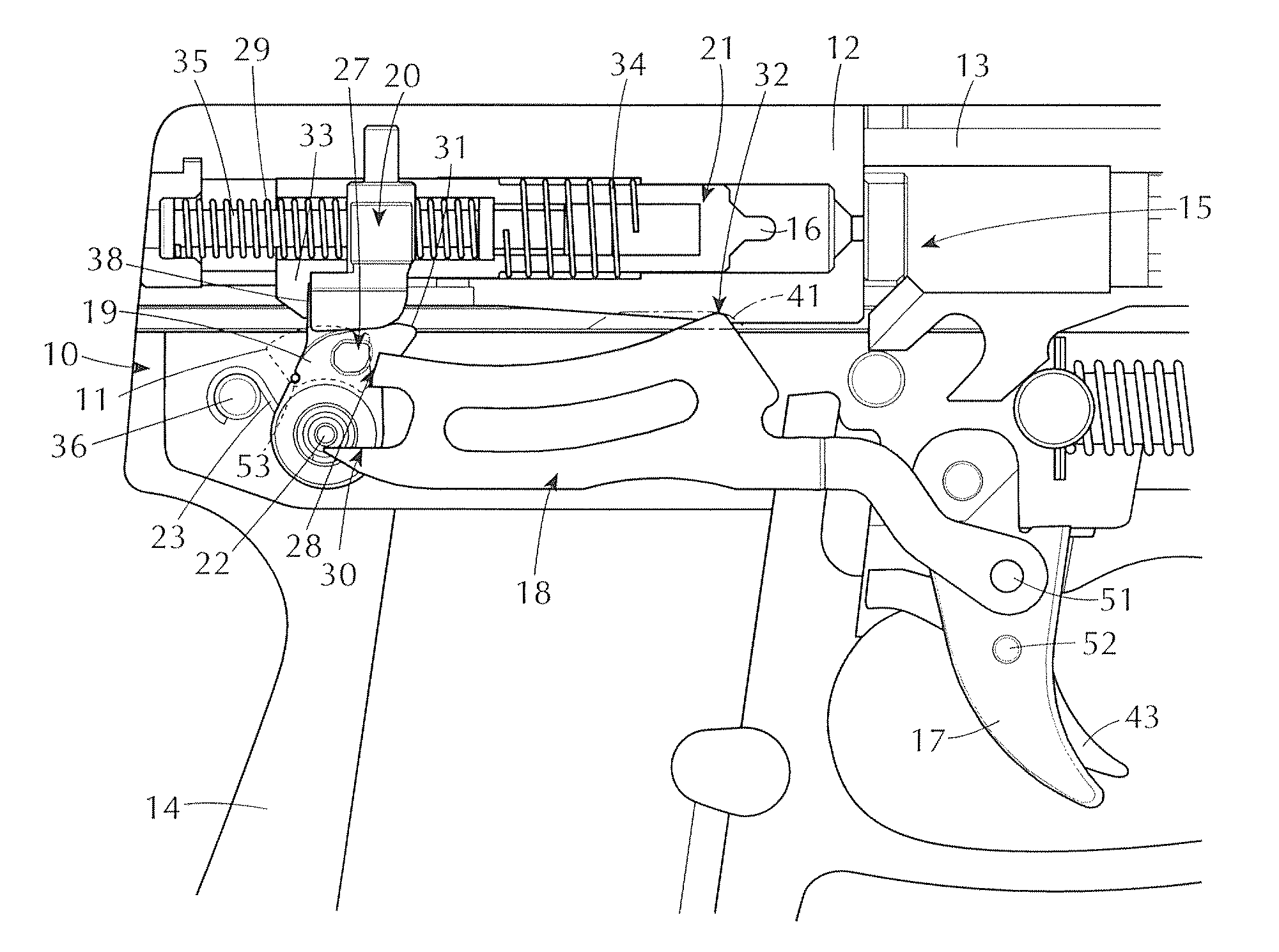
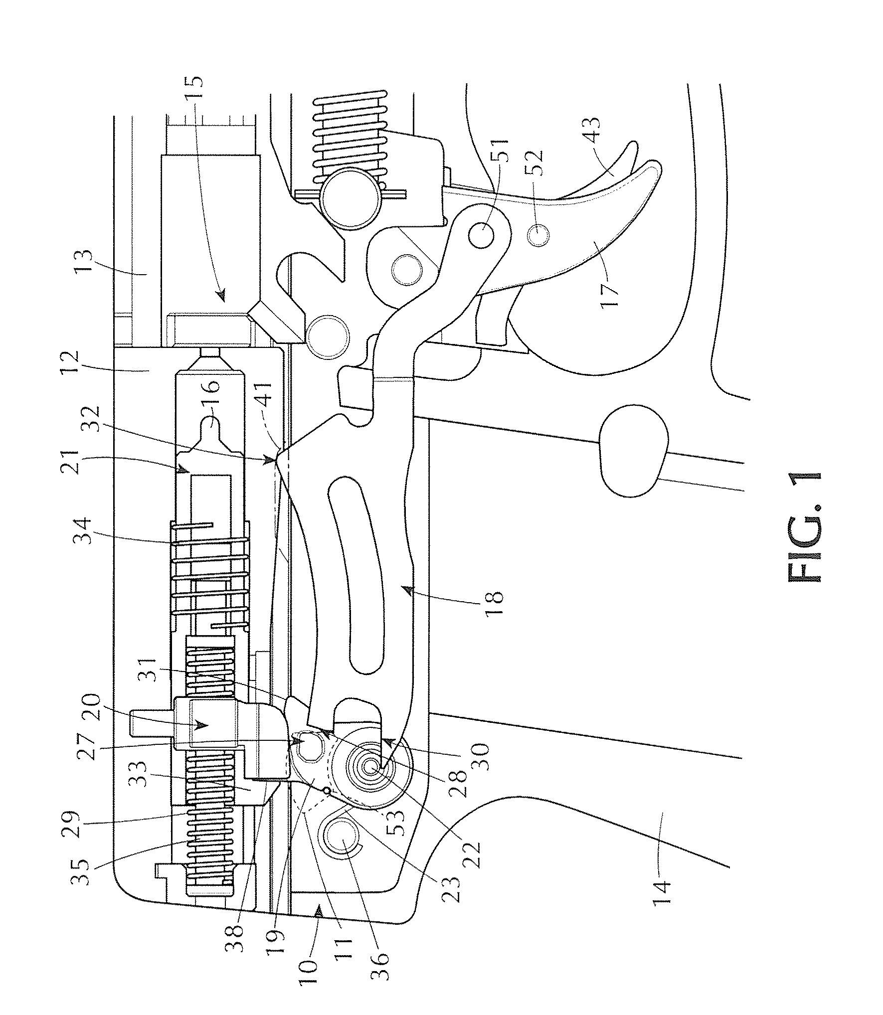
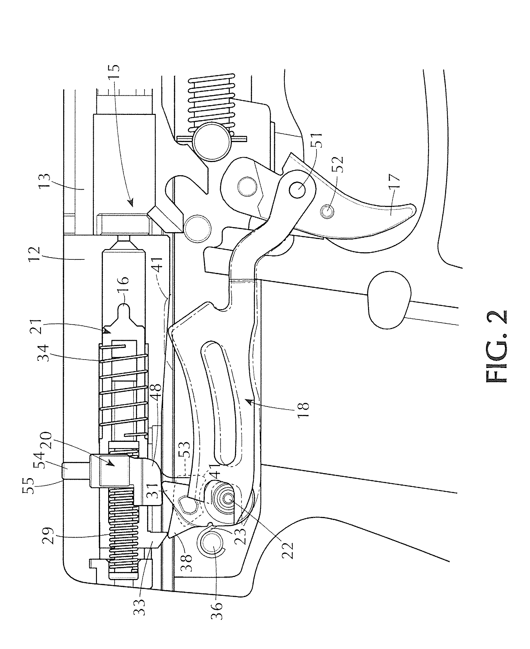
[0022]As shown in FIGS. 1 and 2, the pistol body of the present invention, of generally conventional semi-automatic pistol construction, includes a frame 10 (advantageously of plastic to reduce the overall weight) in which a receiver 11 is mounted. A reciprocating slide 12 and gun barrel 13 are supported on the frame in conventional manner. A spring loaded magazine (not shown) containing ammunition may be inserted in the hollow pistol grip 14 to supply bullets sequentially to the firing chamber 15 in known fashion with each reciprocation of the slide 12. The gun is fired by actuating the striker pin 16 through a new and improved cocking / de-cocking mechanism incorporated into a fundamental striker-pin fired semi-automatic pistol, and including a trigger 17 biased by trigger spring 44, trigger bar 18, multi-purpose cocking lever 19, striker safety block 20, and de-cocking pin 22 which supports the cocking lever.

[0023]The pistol frame 10 (advantageously of molded plastic construction) ...


PUM


Abstract

A cocking / de-cocking mechanism for semi-automatic striker-fired pistols having a multi-function cocking lever for controlling, by rotational movement, the cocking or arming of the tiring pin, while effecting de-cocking by the lateral displacement of the cocking lever on its support pin.

Description

FIELD OF THE INVENTION[0001]The present invention is directed to a safety mechanism in the nature of an improved cocking and de-cocking assembly for striker-fired pistols enabling the striker to be de-cocked with ease and speed for safe field stripping of the weapon.BACKGROUND OF THE INVENTION[0002]Safety mechanisms for pistols have been developed for both hammer-fired and striker-fired semi-automatic weapons to prevent accidental discharge should the weapon fall, be dropped, or otherwise be subject to a sudden application of a stray force. Among the mechanisms developed for this objective are locking or blocking members associated with the trigger and / or firing pin to prevent such accidental discharge. It is to an improved cocking / de-cocking arrangement for striker-fired pistols to which the present invention is specifically directed. The new and improved arrangement permits striker-fired pistols to be simply disassembled without having to pull the trigger, a potentially dangerous ...

Claims


Application Information

Patent Timeline
Patent Type & Authority Applications(United States)
IPC IPC(8): F41A19/39
CPCF41A17/72F41A19/35F41A19/32
Inventor GENTILINI, CLAUDIOKELLOGG, JASON
Owner BERETTA USA CORP
Why Eureka
Try Eureka