
Leak test probe for use in industrial facilities

a technology for industrial facilities and leak detection, applied in the direction of measuring devices, instruments, structural/machine measurement, etc., can solve the problems of power loss exceeding one megawatt per turbine, difficult leak testing of power plant components, and deterioration of vacuum level, so as to achieve high reliability and efficient leak test process, save time and money

Inactive Publication Date: 2011-12-01
AGILENT TECH INC
View PDF2 Cites 16 Cited by
  • Summary
  • Abstract
  • Description
  • Claims
  • Application Information

AI Technical Summary

Benefits of technology

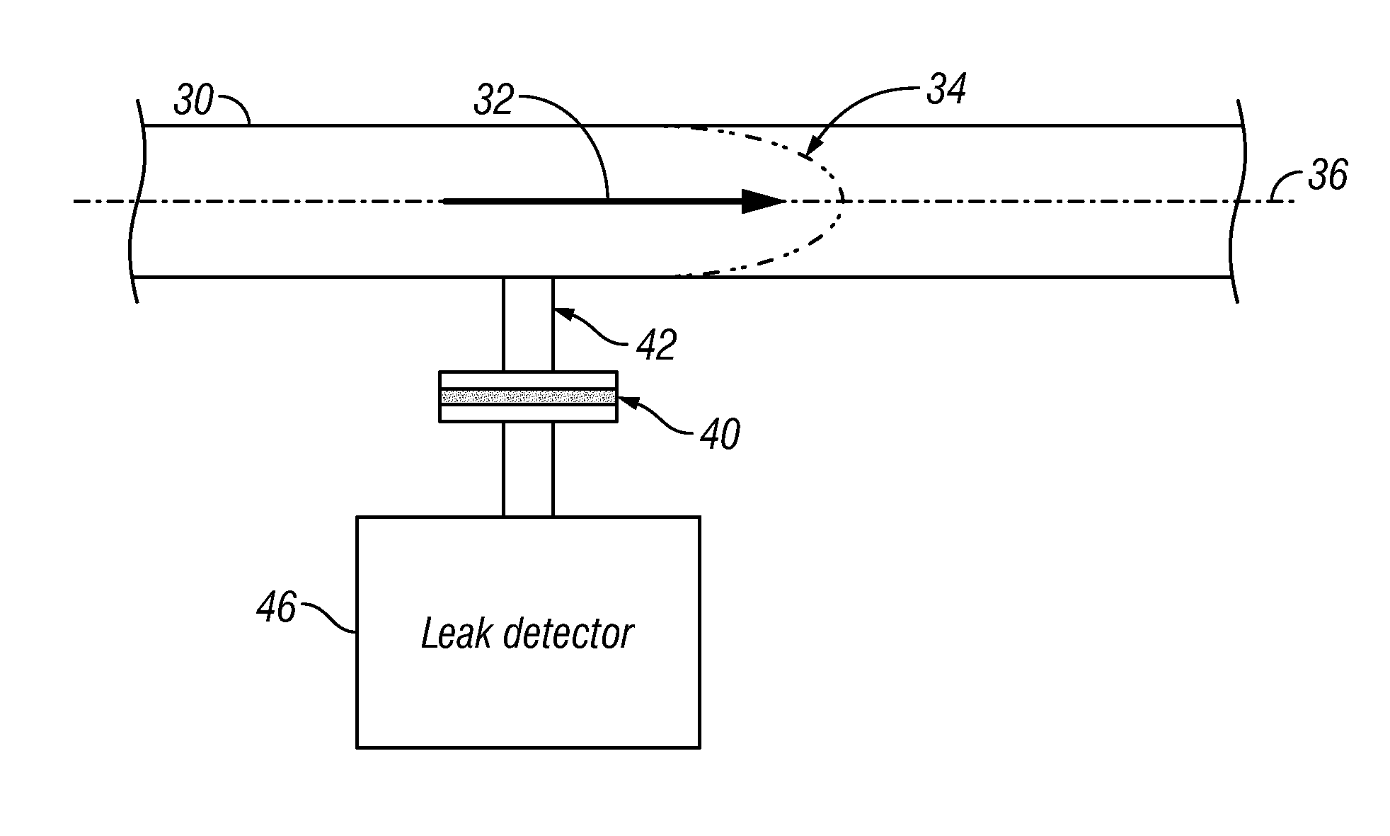
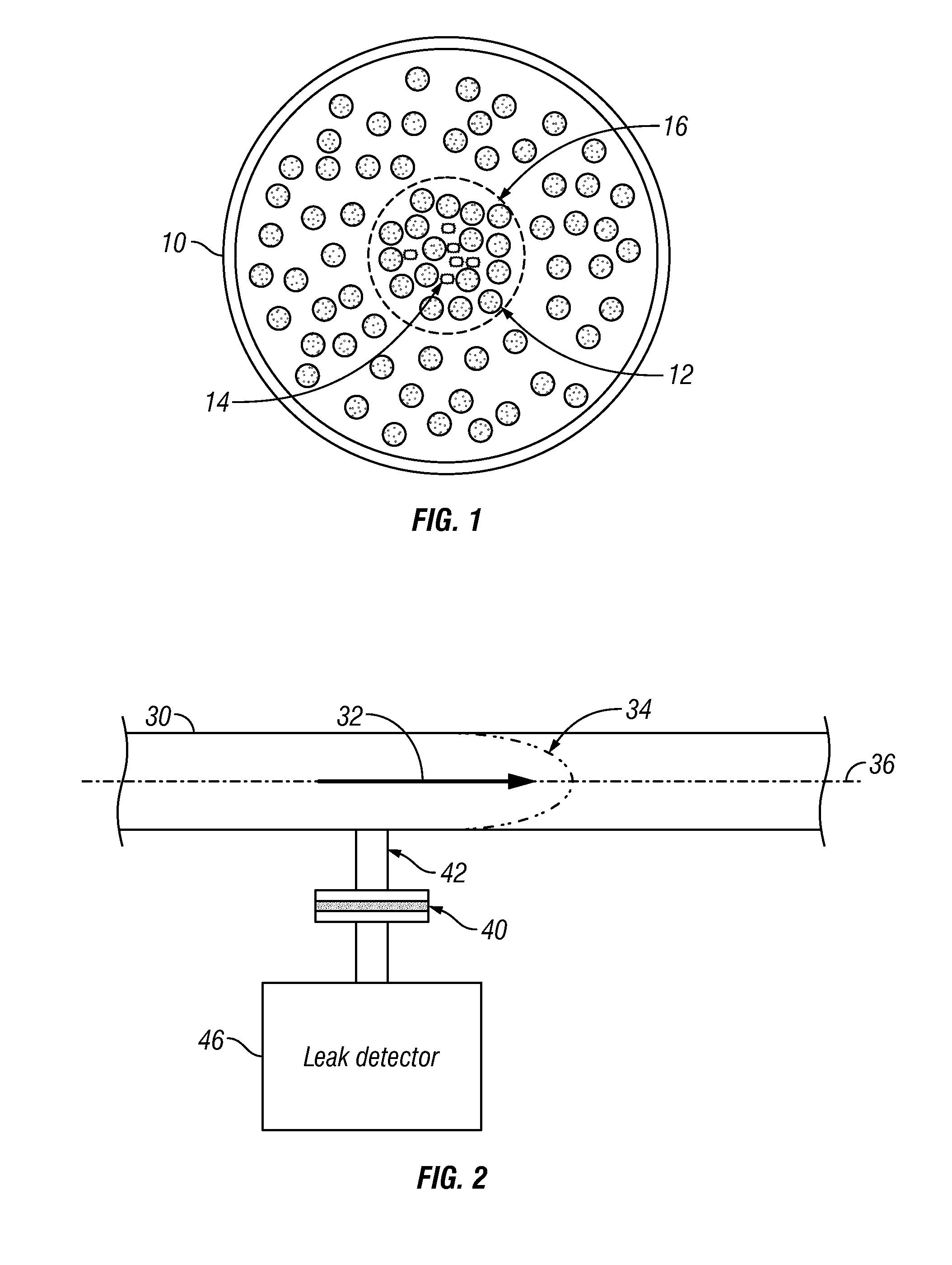
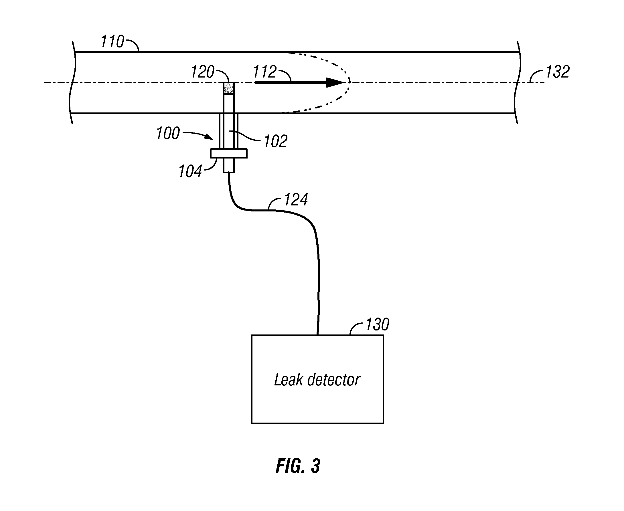
[0010]The present invention provides methods and apparatus to perform accurate, repeatable leak test measurements in wet, dusty and / or fluid-filled systems, such as a power plant, with no special sampling pumps, carrier gases or separators required. A leak detector probe is installed directly in a pipe or other component carrying a gas flow to be tested and is coupled to the inlet of a leak detector, yielding a simple, highly reliable and efficient leak test process. The leak detector probe includes a test gas permeable membrane, which is positioned in the gas flow to be tested. The test gas permeable membrane may, for example, be positioned in a central region of a pipe in the flow of gas toward the evacuation pump. In some embodiments, the position of the leak detector probe in the pipe or other component may be adjustable. The ability to perform leak testing during normal plant operation saves time and money, and makes it possible to find leaks that might not be found when the system is tested at a non-operating pressure.

Problems solved by technology

Leaks in pipes and flanges of the system can result in power loss in excess of one megawatt per turbine.
However, leak testing of power plant components presents a challenging set of problems.
As a result of air in-leakage, the vacuum level can deteriorate and degrade the system efficiency.
However, a known problem in the industry makes accurate and reliable leak testing difficult.
Power plant condenser systems are extremely large, with many pipes and flanges, all of which can leak.
Due to atmospheric air convection, the effects of wind, etc., only a small amount of the helium sprayed actually enters the leak, and enshrouding a section of a large power plant to provide a controlled helium atmosphere is not practical.
In addition, the system contains large amounts of water vapor and amines, which add to the difficulty in testing.
In power plant condensers and other industrial facilities, the volume of gas is very large in comparison to the small amount of test gas entering the system and thus is difficult to detect.
All of the prior art approaches have resulted in complex and expensive systems that are difficult to move around in a large, multi-story power plant complex and do not provide sufficiently reliable test results.

Method used


Image

  • Leak test probe for use in industrial facilities
  • Leak test probe for use in industrial facilities
  • Leak test probe for use in industrial facilities

Examples


Embodiment Construction

[0023]The present invention provides methods and apparatus for performing accurate, repeatable leak test measurements in wet, dusty and / or fluid-filled systems, such as a power plant. A leak detector probe is installed directly into the pipe or other component carrying a gas flow to be tested and is coupled to the inlet of a leak detector, yielding a simple, highly reliable and efficient leak test process. The leak detector probe includes a test gas permeable membrane, which is positioned in the gas flow to be tested. The test gas permeable membrane may, for example, be positioned in a central region of a pipe in the flow of gas toward the evacuation pump. In some embodiments, the position of the leak detector probe in the pipe or other component may be adjustable. The ability to perform leak testing during normal plant operation saves time and money, and makes it possible to find leaks that might not be found when the system is tested at non-operating pressure.

[0024]The gas dynamic...


PUM


Abstract

Methods and apparatus are provided for performing accurate, repeatable leak test measurements in wet, dusty and / or fluid-filled systems, such as a power plant, with no special sampling pumps, carrier gases or separators required. A leak detector probe is installed directly in a pipe or other component carrying a gas flow to be tested and is coupled to the inlet of a leak detector. The leak detector probe includes a test gas permeable membrane, which is positioned in the gas flow to be tested. The test gas permeable membrane may, for example, be positioned in a central region of a pipe in the flow of gas toward the evacuation pump. In some embodiments, the position of the leak detector probe in the pipe or other component may be adjustable.

Description

FIELD OF THE INVENTION[0001]This invention relates to detection of leaks in large piping systems operating below atmospheric pressure and, more particularly, to methods and apparatus for test gas leak detection in industrial facilities, such as power plant systems, for example.BACKGROUND OF THE INVENTION[0002]Helium mass spectrometer leak detection is a well-known leak detection technique. Helium is used as a test gas, which passes through the smallest of leaks in a sealed test piece. After passing through the leak, a test sample containing helium is drawn into a leak detection instrument and is measured. In the instrument, a mass spectrometer or other detector detects and measures the helium. In one approach, a test piece is pressurized with helium. A leak detector probe, or “sniffer probe”, connected to the test port of the leak detector is moved around the exterior of the test piece. Helium passes through leaks in the test piece, is drawn into the probe and is measured by the lea...

Claims


Application Information

Patent Timeline
IPC IPC(8): G01M3/20
CPCG01M3/222G01M3/205
Inventor PERKINS, CHARLESPALENSTYN, PIETER
Owner AGILENT TECH INC
Learn More