Cabled matrix for cantilevered photovoltaic solar panel arrays, apparatus and deployment systems

a photovoltaic solar panel and array technology, applied in the field of modular structure for supporting solar energy conversion systems, can solve the problems of photovoltaic solar panels and the failure of the structure to provide a longer span, and achieve the effect of prolonging the life of the wiring and high strength-to-weight ratio

Inactive Publication Date: 2011-12-01
HOFFMANN STEVE +2
View PDF0 Cites 38 Cited by
  • Summary
  • Abstract
  • Description
  • Claims
  • Application Information

AI Technical Summary

Benefits of technology

[0027]In one embodiment of the present invention, a composite end girder is provided to provide a high strength-to-weight ratio beam at the edges, which will allow for a molding with alternative style treatments.
[0028]In another embodiment of the present invention, a lighting housi...

Problems solved by technology

Structures known in the art which utilize photovoltaic solar panels to ...

Method used


Image

  • Cabled matrix for cantilevered photovoltaic solar panel arrays, apparatus and deployment systems
  • Cabled matrix for cantilevered photovoltaic solar panel arrays, apparatus and deployment systems
  • Cabled matrix for cantilevered photovoltaic solar panel arrays, apparatus and deployment systems

Examples


Embodiment Construction

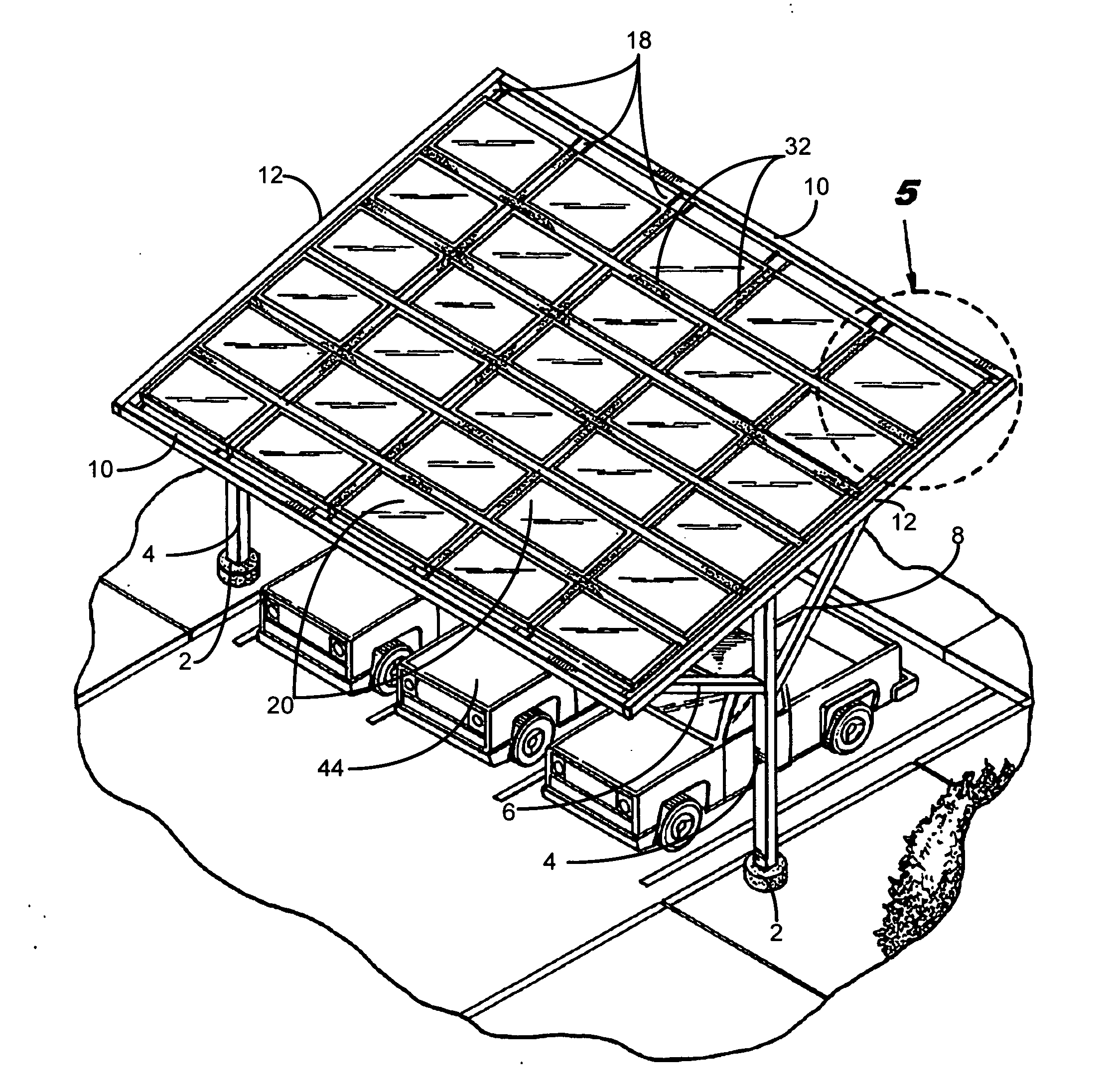
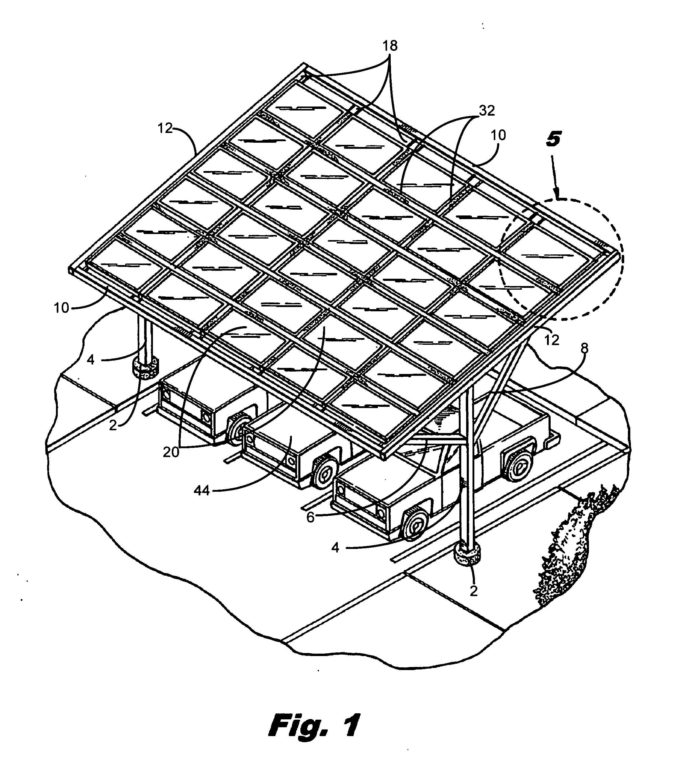
[0050]In accordance with the subject invention, FIG. 1 shows one embodiment of the present invention in which a plurality array bracing beams define a perimeter of a matrix array. In this embodiment, the array bracing means include at least two longitudinal array bracing beams 12 and at least two latitudinal array bracing beams 10. It will be recognized by one of ordinary skill in the art that the number of longitudinal array bracing beams 12 and latitudinal array bracing beams 10 may be varied based upon the desired configuration of the cabled matrix of the present invention. For example, the number of longitudinal array bracing beams 12 and latitudinal array bracing beams 10 may be varied based upon the number of sides in the cabled matrix.

[0051]Latitudinal array bracing beams 10 include coupling apertures 50 at various points along each latitudinal array bracing beam 10. In one particular embodiment of the present invention, coupling apertures 50 are disposed at opposing points o...


PUM


Abstract

A cable reinforced matrix to support a solar panel array comprising array bracing beams which define a perimeter including longitudinal array bracing beams and latitudinal array bracing beams with coupling apertures at various points along the latitudinal array bracing beams; cable couplings at opposite points along the latitudinal array bracing beams; cabling traversing the latitudinal array bracing beams; solar panels atop the cabling; longitudinal I-beams; latitudinal I-beams; interpanel I-beam(s); grommets along the cabling; grommet clips; grommet clip fasteners; panel fasteners; columns at either end of the longitudinal array bracing beams; a first cantilever support post extending from the column to the distal portion of the longitudinal array bracing beam; a second cantilever support post extending from the column to the proximal portion of the longitudinal array bracing beam; a footing at the bottom of each column; and dampening/stabilizing element(s) to mitigate vibration and uplift.

Description

FIELD OF THE INVENTION[0001]The instant invention relates to the field of photovoltaic building and deployment systems, specifically to a modular structure for supporting a solar energy conversion system. The present invention is particularly, but not exclusively, useful as a modular structure for supporting photovoltaic systems to convert solar energy into electricity and to provide shade to an area, such as a carport.BACKGROUND OF THE INVENTION[0002]After analyzing the field of designing, manufacturing, and marketing various solar-related products for nearly a decade, the instant invention has been designed and developed to overcome deficiencies observed with the prior art, as discussed hereinbelow.[0003]Due to the depletion of known reserves of fossil fuels, much research and development has gone into searching for alternative energy sources. One source of alternative energy is solar energy. As a renewable source, solar energy is increasingly popular for use as an electricity sou...

Claims


Application Information

Patent Timeline
IPC IPC(8): H01L31/048
CPCF24J2/045F24J2/5205F24J2/5232F24J2/5241H02S20/23Y02B10/20Y02E10/47F24J2002/4659Y02B10/12F24S20/67F24S25/12F24S25/33F24S25/50F24S25/617F24S2025/6001Y02B10/10Y02E10/50
Inventor HOFFMANN, STEVEWEINER, GEORGEHOFFMANN, STEVEN
Owner HOFFMANN STEVE
Why Eureka
Try Eureka