Method of manufacture by superplastic forming and by fishplating of a rib for an aerodynamic fairing of an aircraft engine mounting pylon

Inactive Publication Date: 2011-12-01
AIRBUS OPERATIONS SAS
View PDF3 Cites 19 Cited by
  • Summary
  • Abstract
  • Description
  • Claims
  • Application Information

AI Technical Summary

Benefits of technology

The invention is essentially remarkable in that it enables a thin rib to be obtained through the use of the rib preform by superplastic forming, and enables it to be given precise tolerances by joining the two rib preform half-parts by fishplating.
The step of division is preferably undertaken in such a way that the two straight-line segments are supported by a given diagonal of the quadrilateral. An alternative embodiment clearly consists in making them parallel, but of

Problems solved by technology

It has the advantage of giving precise tolerances, but does not enable thin ribs to be obtained.
Indeed, below a cert

Method used


Image

  • Method of manufacture by superplastic forming and by fishplating of a rib for an aerodynamic fairing of an aircraft engine mounting pylon
  • Method of manufacture by superplastic forming and by fishplating of a rib for an aerodynamic fairing of an aircraft engine mounting pylon
  • Method of manufacture by superplastic forming and by fishplating of a rib for an aerodynamic fairing of an aircraft engine mounting pylon

Examples


Embodiment Construction

This description will be made with reference to the attached illustrations, among which

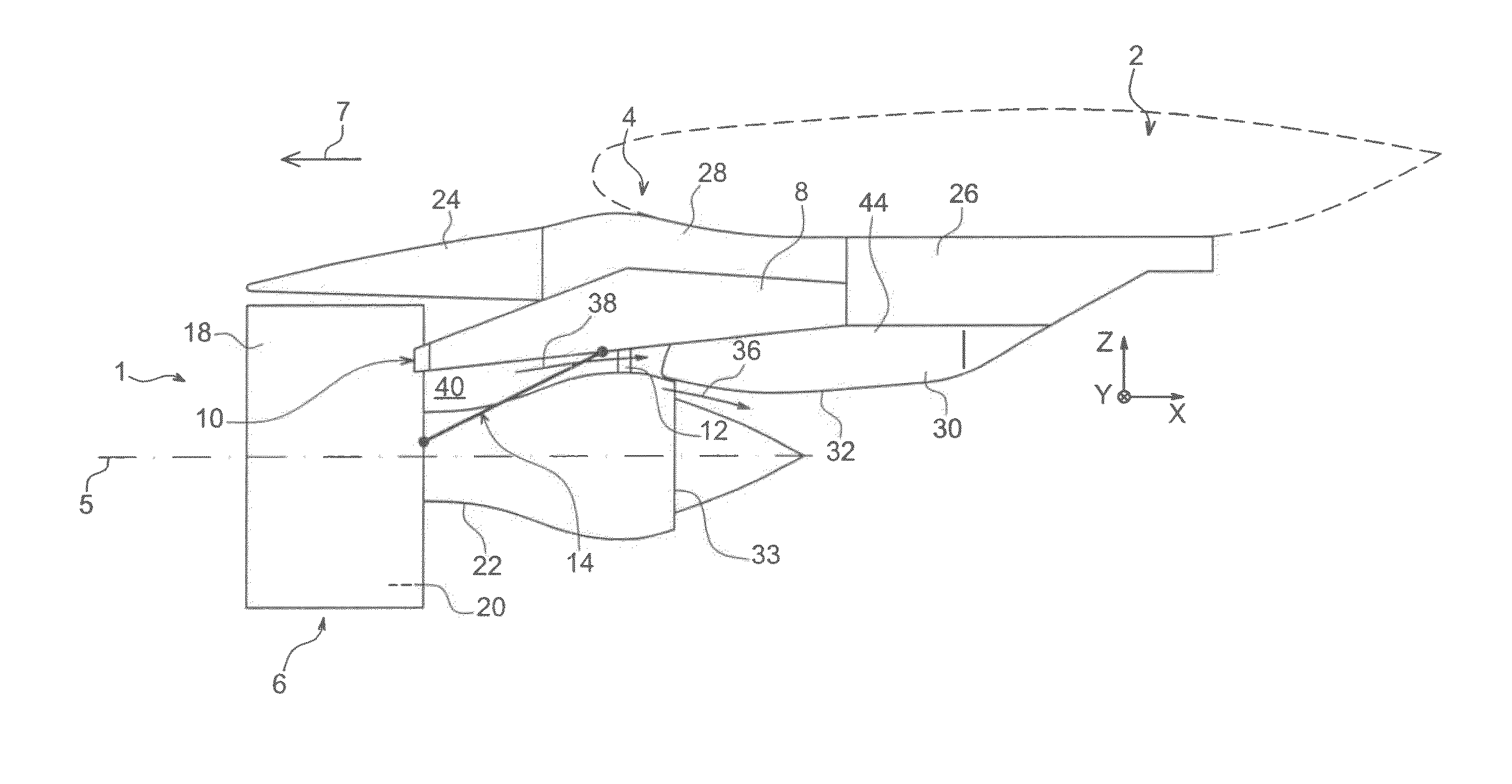
FIG. 1 represents a schematic side view of an aircraft engine assembly, including a mounting device according to a preferred embodiment of the present invention;

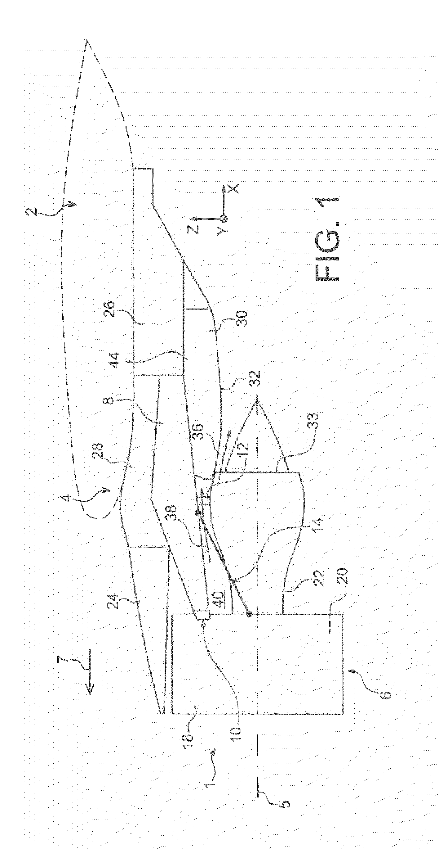
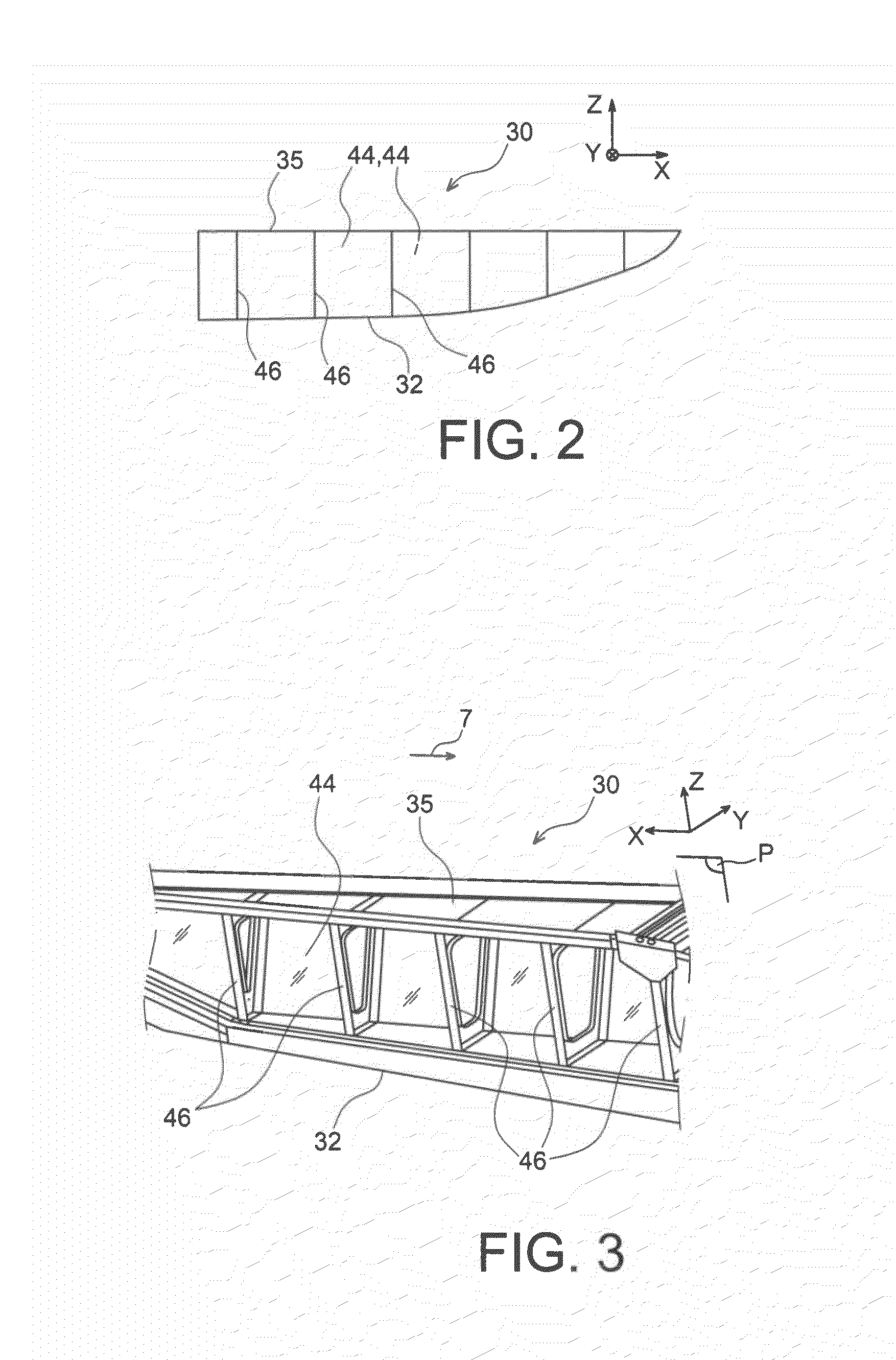
FIG. 2 represents a more detailed sideways schematic view of the lower aft aerodynamic fairing fitted to the mounting device shown in FIG. 1, where this fairing is also the subject of the present invention;

FIG. 3 represents a perspective view of a part of the lower aft aerodynamic fairing in FIG. 2; and

FIGS. 4a to 4d′ represent various steps of a method of manufacture of an internal rib fitted to the fairing shown in FIGS. 2 and 3, where this method takes the form of a preferred embodiment of the present invention.

DETAILED ACCOUNT OF PREFERRED EMBODIMENTS

With reference to FIG. 1, an aircraft engine assembly 1 can be seen intended to be attached to a wing 2 of this aircraft, where this assembly 1 includes a mounting device 4 according to a ...


PUM


Abstract

The present invention relates to a method of manufacture of a stiffening transverse internal rib for an aerodynamic fairing of an engine mounting device, including:
    • the production of a rib preform by superplastic forming having an outline of a broadly quadrilateral shape, and a central opening (52) traversing this preform;
    • the division of the preform into two parallel straight-line segments (56, 60), which are diagonally opposed, causing the separation into two half-parts (46a′, 46a″) of the rib preform; and
    • fishplating of the two rib preform half-parts (46a′, 46a″) by bolting.

Description

TECHNICAL FIELDThe present invention relates to a lower aft aerodynamic fairing for an engine mounting device intended to be interposed between an aircraft wing surface and the engine concerned, this fairing also being called a “shield” or “APF” (“Aft Pylon Fairing”).Such a mounting device, also called an “EMS” (“Engine Mounting Structure”), allows, for example, a turbine engine to be suspended beneath the wing surface of the aircraft, or allows this turbine engine to be mounted above this same wing surface or, again, allows it to be mounted laterally in the aft part of the fuselage. An example of a mounting device is known from document WO 2009 / 037267.More specifically, the invention relates to the transverse internal stiffener ribs which are fitted to the lower aft aerodynamic fairing, and more specifically to their method of manufacture.The invention may be used in any type of aircraft fitted with turbojets or turboprop engines.STATE OF THE PRIOR ARTA mounting device is, indeed, ...

Claims


Application Information

Patent Timeline
IPC IPC(8): B64D27/00B64C1/38
CPCB64D27/18B64D33/04B64F5/00
Inventor MACHADO, STEPHANERAISON, FABIENROMANI, STEPHANE
Owner AIRBUS OPERATIONS SAS
Why Eureka
Try Eureka