Organic light emitting diode display and method for compensating chromaticity coordinates thereof

Active Publication Date: 2011-12-01
LG DISPLAY CO LTD
View PDF7 Cites 20 Cited by
  • Summary
  • Abstract
  • Description
  • Claims
  • Application Information

AI Technical Summary

Benefits of technology

[0011]The present invention has been made in an effort to provide an organic light emitting diode display, which can compensate for deviations i

Problems solved by technology

However, the larger the size of the substrate, the more the mask is bent.
Thus, the conventional deposition method using a metal mask decreases yield because it makes it difficult to precisely pattern an emission lay

Method used


Image

  • Organic light emitting diode display and method for compensating chromaticity coordinates thereof
  • Organic light emitting diode display and method for compensating chromaticity coordinates thereof
  • Organic light emitting diode display and method for compensating chromaticity coordinates thereof

Examples


Embodiment Construction

[0034]Hereinafter, an implementation of this document will be described in detail with reference to FIGS. 4 to 16.

[0035]FIG. 4 shows an organic light emitting diode display according to an exemplary embodiment of the present invention. FIG. 5 shows various array patterns of sub-pixels in one pixel, and FIG. 6 shows a laminated configuration of sub-pixels in one pixel.

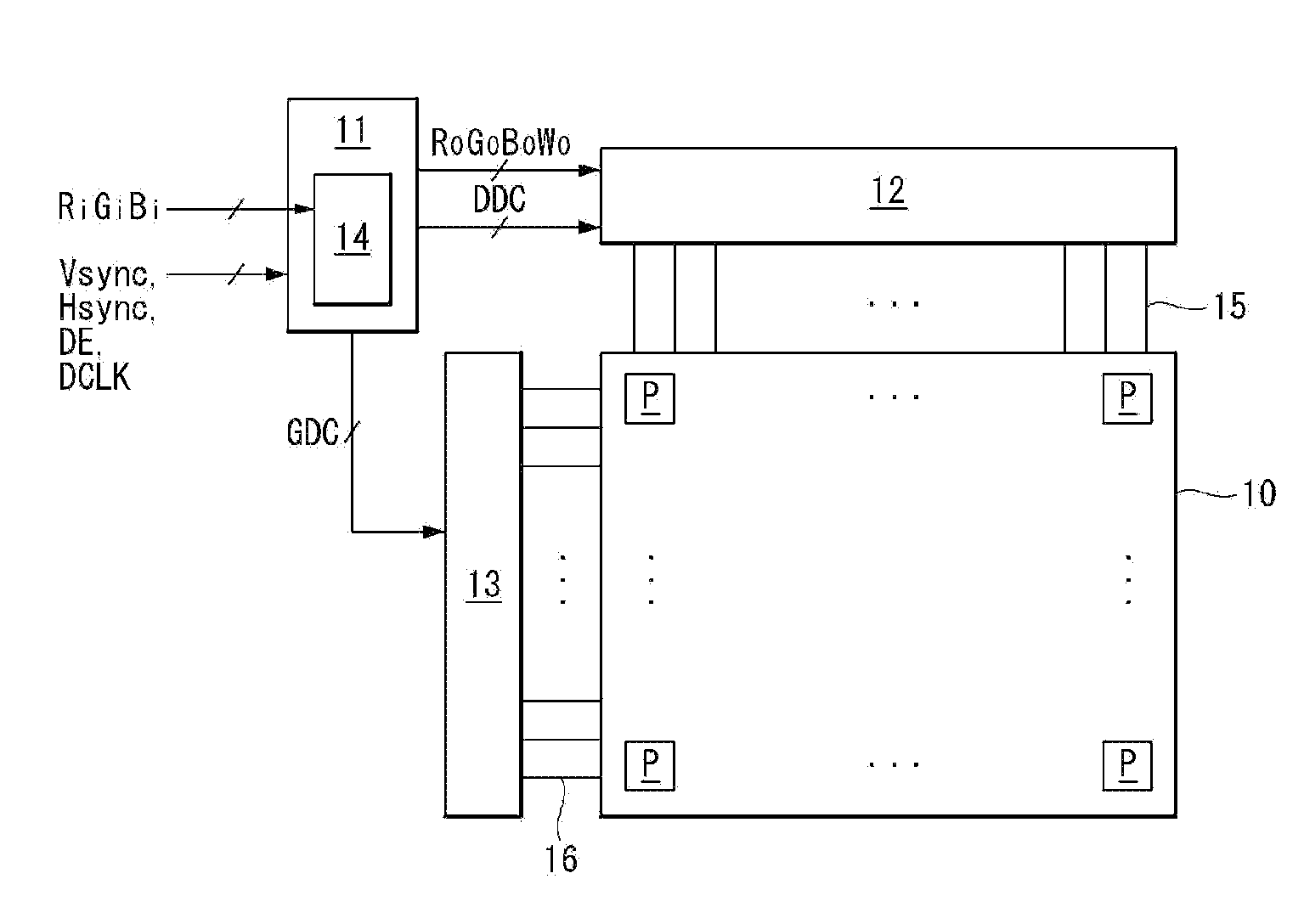
[0036]Referring to FIGS. 4 to 6, this organic light emitting diode display comprises a display panel 10, a timing controller 11, a data drive circuit 12, a gate drive circuit 13, and a chromaticity coordinate compensation circuit 14.

[0037]In the display panel 10, a plurality of data lines 15 and a plurality of gate lines 16 cross each other, and pixels P each comprising four sub-pixels SPr, SPg, SPb, and SPw are arranged in pixel areas defined by the crossings thereof. A pixel P comprises an R sub-pixel SPr for generating R (red) light, a G sub-pixel SPg for generating G (green) light, a B sub-pixel SPb for generating B...


PUM


Abstract

An organic light emitting diode display, comprising: a display panel on which a plurality of pixels are arranged, each of the pixels comprising an R sub-pixel for generating red light through a white OLED and an R color filter, a G sub-pixel for generating green light through a white OLED and a G color filter, a B sub-pixel for generating blue light through a white OLED and a B color filter, and a W sub-pixel for generating white light through a white OLED; a data operation unit for generating a data operation value by extracting a representative value for each pixel based on three primary color data, determining white data of the corresponding pixel as the representative value, and then subtracting the white data from the three primary color data for each pixel; a gain adjusting unit for generating a gain adjusting value of the three primary color data by multiplying a preset gain value of the three primary color data by the corresponding white data; and a data conversion unit for generating four color compensation data, whose white chromaticity coordinates are compensated for each pixel, by adding the gain adjusting value to the data operation value and matching the corresponding white data to the three primary color data converted by the adding.

Description

[0001]This application claims the benefit of Korea Patent Application No. 10-2010-0049607 field on May 27, 2010, which is incorporated herein by reference for all purposes as if fully set forth herein.BACKGROUND[0002]1. Field[0003]This document relates to an organic light emitting diode display and a method for compensating the chromaticity coordinates thereof.[0004]2. Related Art[0005]An active matrix type organic light emitting diode display (AMOLED) is attracting a lot of attention as a next generation display because of advantages of fast response speed, high light emission efficiency, high luminance, and wide viewing angle. The organic light emitting diode display displays an image by controlling a current, flowing in an organic light emitting diode (hereinafter, OLED) by using a thin film transistor (hereinafter, referred to as “TFT”).[0006]A typical organic light emitting diode display has a plurality of pixels, each comprising an R (red) sub-pixel, a G (green) sub-pixel, and...

Claims


Application Information

Patent Timeline
IPC IPC(8): G09G5/10G09G3/30
CPCG09G3/3225G09G2300/0452G09G2340/06G09G2320/0666G09G2320/0242
Inventor LIM, HOMIN
Owner LG DISPLAY CO LTD
Why Eureka
Try Eureka