Magnetic head and magnetic disk drive to be used for shingled recording method

a magnetic disk drive and recording method technology, applied in the field of magnetic disk drives and recording heads, can solve the problems of increasing bit error rate, reducing the frequency of recording magnetic field induced by recording heads, and unable to write sufficient recording media, so as to reduce the signal resolution, reduce the signal-to-noise ratio, and reduce the bit error rate

Inactive Publication Date: 2011-12-01
HITACHI LTD
View PDF9 Cites 22 Cited by
  • Summary
  • Abstract
  • Description
  • Claims
  • Application Information

AI Technical Summary

Benefits of technology

[0022]Even in this case, degradation of a signal resolution and a decrease in a signal-to-noise ratio which are derived from a transition curvature can be suppressed, and a bit error rate can be decreased.
[0023]In the present invention, the tilt angle θ of the gap between the magnetic shields or the tilt angle θ of the two magnetic field sensing layers and differential intermediate layer falls within a range within which the tilt angle θ is 0 to 2.5 times larger than a mean angle α of an inter-bit transition curvature in a record pattern. Therefore, compared with an existing structure in which a magn

Problems solved by technology

However, when the pole width of a recording head is narrowed in order to increase the track density, that is, in order to narrow the record track width, the intensity of a recording magnetic field induced by the recording head is generally decreased, and a sufficient ability to write the recording media becomes unavailable

Method used


Image

  • Magnetic head and magnetic disk drive to be used for shingled recording method
  • Magnetic head and magnetic disk drive to be used for shingled recording method
  • Magnetic head and magnetic disk drive to be used for shingled recording method

Examples


first embodiment

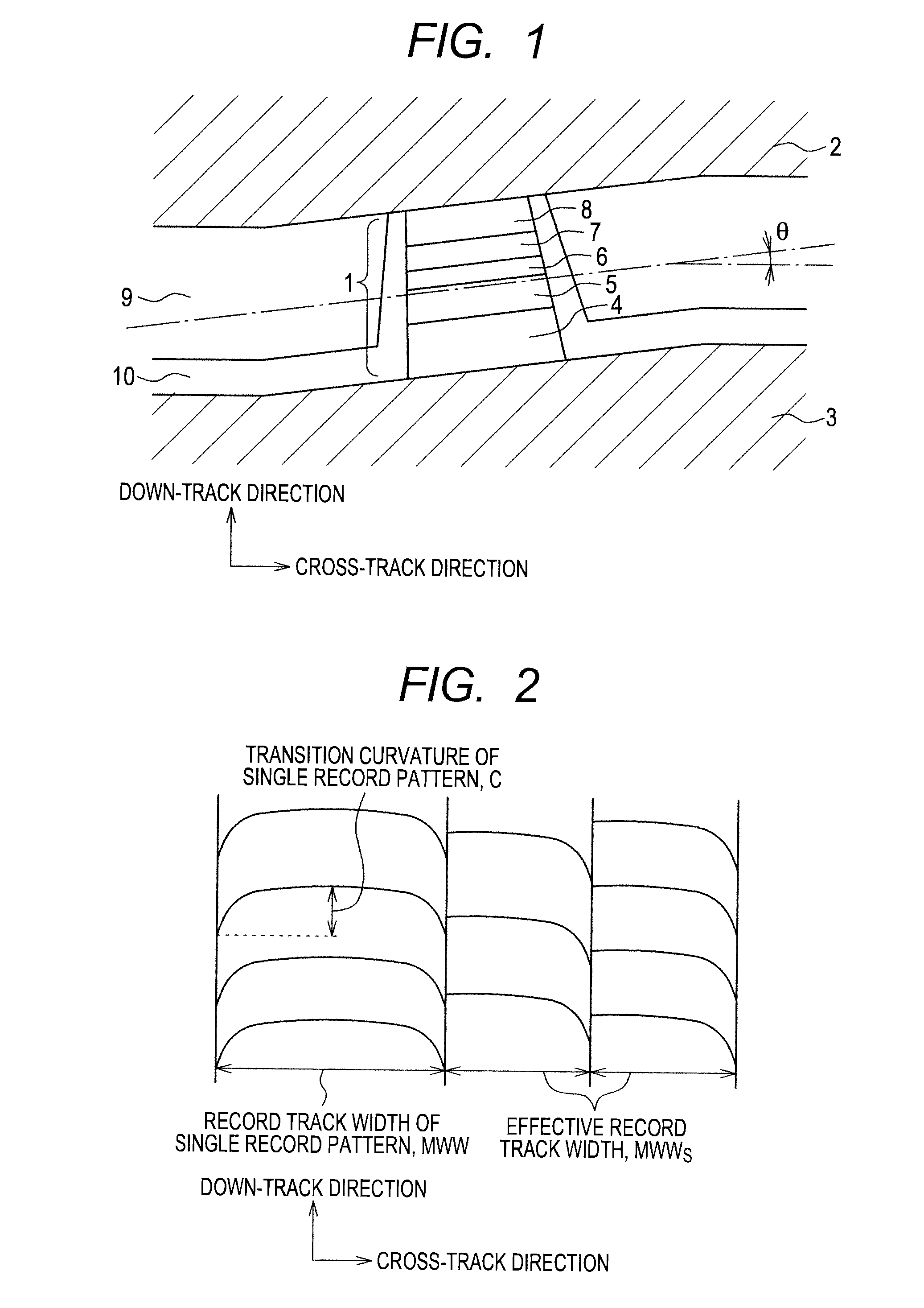
[0041]FIG. 2 is an illustrative diagram of a record track recorded according to a shingled recording method. As shown in FIG. 2, the magnitude of a transition curvature C in a single record pattern is defined as a difference between the center of the record pattern, which is not overwritten, and a transitional position in a recording down-track direction at an edge of the record pattern. In comparison with a record track width MWW of the single record pattern one side of which is not overwritten, a record track width of the single record pattern one side of which is overwritten shall be called an effective record track width MWWs. In FIG. 2, the left sides of record patterns are sequentially overwritten. Alternatively, the right sides of the record patterns may be sequentially overwritten. As shown in FIG. 2, since one side of a record track is overwritten according to the shingled recording method, an inter-bit transition in the down-track direction on an effective record track on ...

second embodiment

[0072]FIG. 9 is an illustrative diagram showing a medium opposite surface of a reproducing head having an example of a second construction in accordance with the present invention.

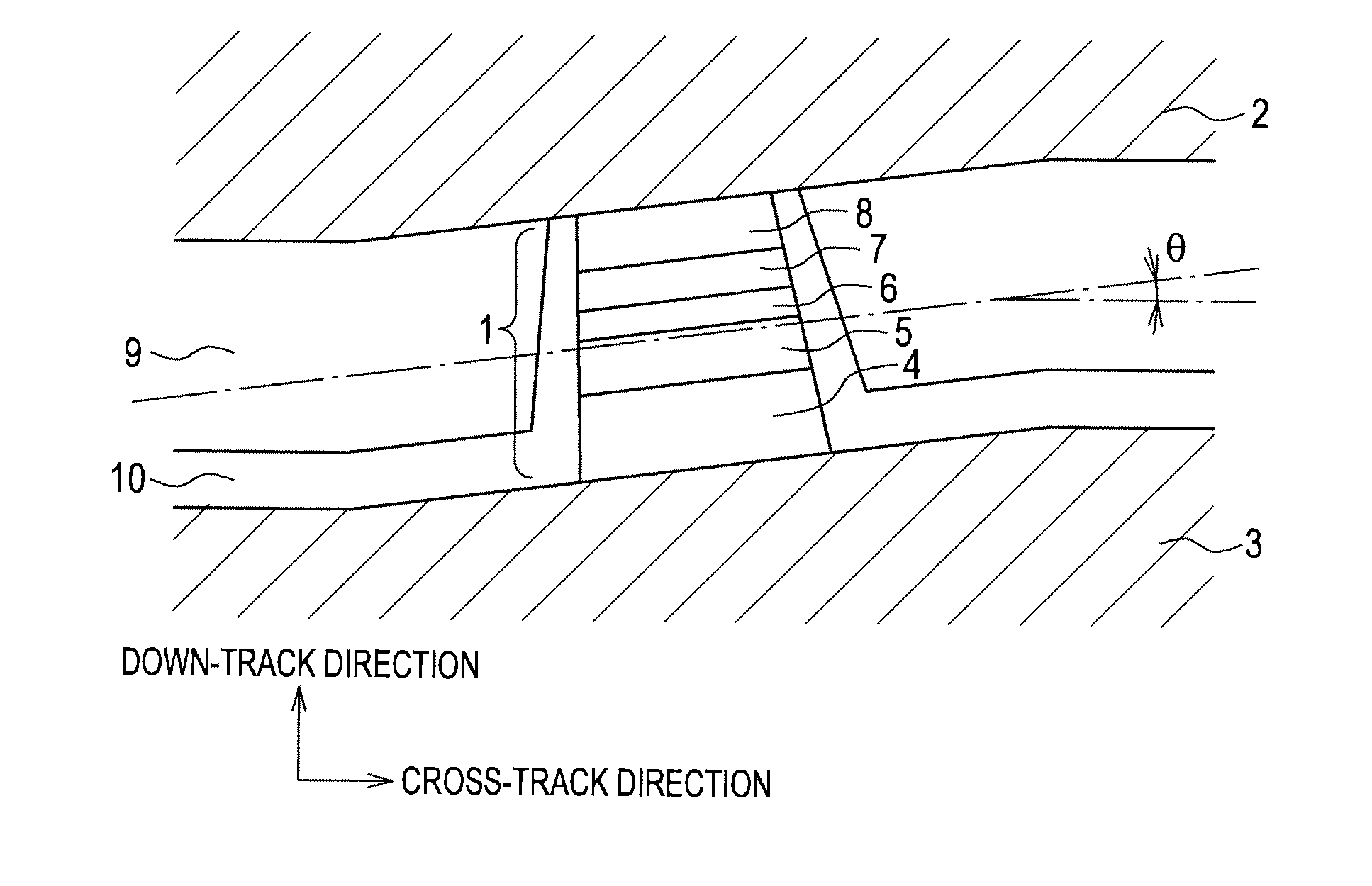
[0073]The reproducing head includes a sensor 11 that senses a signal magnetic field induced from a recording medium, a pair of magnetic shields (an upper magnetic shield 12 and a lower magnetic shield 13), an upper flattening layer 14 interposed between the sensor 11 and upper magnetic shield 12, and a lower flattening layer 15 interposed between the sensor 11 and lower magnetic shield 13. The gap between the magnetic shields is formed to tilt with respect to a cross-track direction in line with a transition curvature of an effective record pattern. The upper magnetic shield 12 and lower magnetic shield 13 are made of a soft magnetic material represented by a NiFe alloy exhibiting a high permeability. The upper flattening layer 14 and lower flattening layer 15 are layers for use in flattening the sensor 11...

third embodiment

[0081]A third embodiment is implemented in a differential type reproducing head having two sensors juxtaposed in a down-track direction with an appropriate space between them. In the differential type reproducing head, each of the two sensors senses a signal magnetic field induced from a medium, and a difference between the outputs of the two sensors is acquired as a final output of the reproducing head. For example, when the two sensors lie on the same bit in the down-track direction, the two sensors generate outputs of opposite positive and negative polarities. As a result, when the two sensors lie on the same bit in the down-track direction, the difference between the outputs thereof is null, and the output of the entire reproducing head is null. In contrast, at an instant when the two sensors lie on different bits in the down-track direction, the outputs of the two sensors exhibit the same polarity. Therefore, the difference between the outputs of the two sensors is not null, bu...


PUM


Abstract

In a magnetic head to be used for a shingled recording method, degradation of a signal resolution and a decrease in a signal-to-noise ratio which are caused by an asymmetrical inter-bit transition curvature are prevented, and a low bit error rate is realized. A magnetic head includes a recording head and a reproducing head. The reproducing head includes a pair of magnetic shields and a sensor sandwiched between the pair of magnetic shields. The gap between the magnetic shields is formed so that the longitudinal direction thereof gets inclined by a certain angle with respect to a cross-track direction in line with the shape of a curvature of an inter-bit transition on an effective record track in a record pattern recorded on a recording medium.

Description

CLAIM OF PRIORITY[0001]The present application claims priority from Japanese patent application JP2010-124342 filed on May 31, 2010, the content of which is hereby incorporated by reference into this application.BACKGROUND OF THE INVENTION[0002]1. Field of the Invention[0003]The present invention relates to a magnetic head and a magnetic disk drive, or more particularly, to a magnetic head and a magnetic disk drive which are used for a shingled recording method.[0004]2. Description of the Related Art[0005]For increasing the storage capacity of a magnetic recording device represented by a hard disk drive, it is necessary to improve a recording density for information to be recorded in recording media. In order to improve the recording density, there is made an approach that the width of a record track recorded in the medium is narrowed to increase a track density, or that a bit length on the record track is shortened, that is, a linear recording density is increased. However, when th...

Claims


Application Information

Patent Timeline
IPC IPC(8): G11B5/10
CPCG11B5/1278G11B5/3967G11B5/3912
Inventor KATADA, HIROYUKIICHIHARA, TAKAYUKIKAWATO, YOSHIAKI
Owner HITACHI LTD
Why Eureka
Try Eureka