Combustion apparatus

a technology of combustion apparatus and combustion chamber, which is applied in the direction of combustion types, burners, hollow bar grates, etc., can solve the problems of increasing cost and reducing combustion efficiency, and achieve the effects of increasing the number of parts, increasing combustion efficiency, and increasing combustion velocity

Inactive Publication Date: 2011-12-08
RINNAI CORP
View PDF15 Cites 7 Cited by
  • Summary
  • Abstract
  • Description
  • Claims
  • Application Information

AI Technical Summary

Benefits of technology

[0007]In order to attain the object mentioned above, an aspect of the present invention is a combustion apparatus, comprising: a combustion housing; a partition plate provided in the combustion housing to partition a space in the combustion housing into a combustion chamber and an air supply chamber on a lower side of the combustion chamber; a plurality of rich-lean burners arranged in a right-left direction of the combustion chamber, each of the rich-lean burners including a burner main body elongated in a front-rear direction thereof, a lean flame port jetting out a lean mixture gas of a fuel concentration leaner than a theoretical air fuel ratio, and a couple of rich flame ports situated on both sides of the lean flame port in a right-left direction thereof to jet out a rich mixture gas of a fuel concentration richer than that of the lean mixture gas, the lean flame port and the rich flame ports being situated at an upper end of the burner main body; a multiplicity of distributed holes formed in the partition plate through which distributed holes secondary air is supplied from the air supply chamber to the combustion chamber; a flame rod facing to an upper side of a part of the rich-lean burners to stop combustion when the flame rod does not detect any flames owing to a flame lift at a time of an oxygen deficiency; wherein a supply quantity of the secondary air to the part of the rich-lean burners to which part the flame rod faces is larger than those to other parts.
[0008]Rich flames formed on the rich flame ports spread out to the outer sides to seek the secondary air at the time of an oxygen deficiency, here. Then, if the supply quantity of the secondary air is large, the rich flames are turned up from the outer sides by the secondary air blowing up to the outer sides of the rich flames. The rich flame ports on the outer sides in the burner main body are, furthermore, cooled by the secondary air, and the combustion velocity becomes slower. Consequently, the lifts of the ri

Problems solved by technology

Then, the flame lifts owing to the oxygen deficiency sometimes advance in a part in which no flame rod is provided owing to the distribution unevenness of a mixture gas

Method used


Image

  • Combustion apparatus
  • Combustion apparatus
  • Combustion apparatus

Examples


Embodiment Construction

[0019]Embodiments of the present invention will be explained with reference to the drawings.

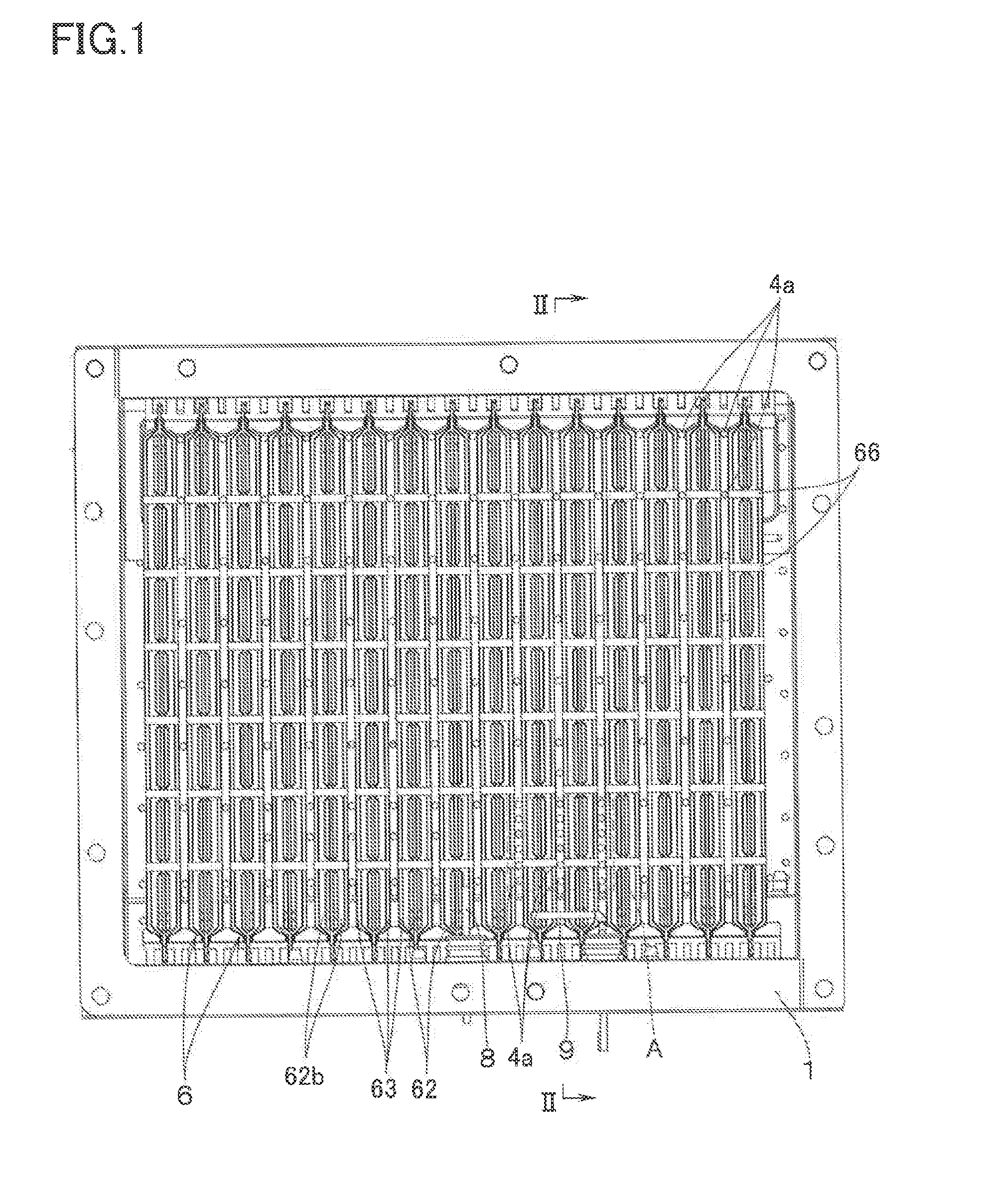
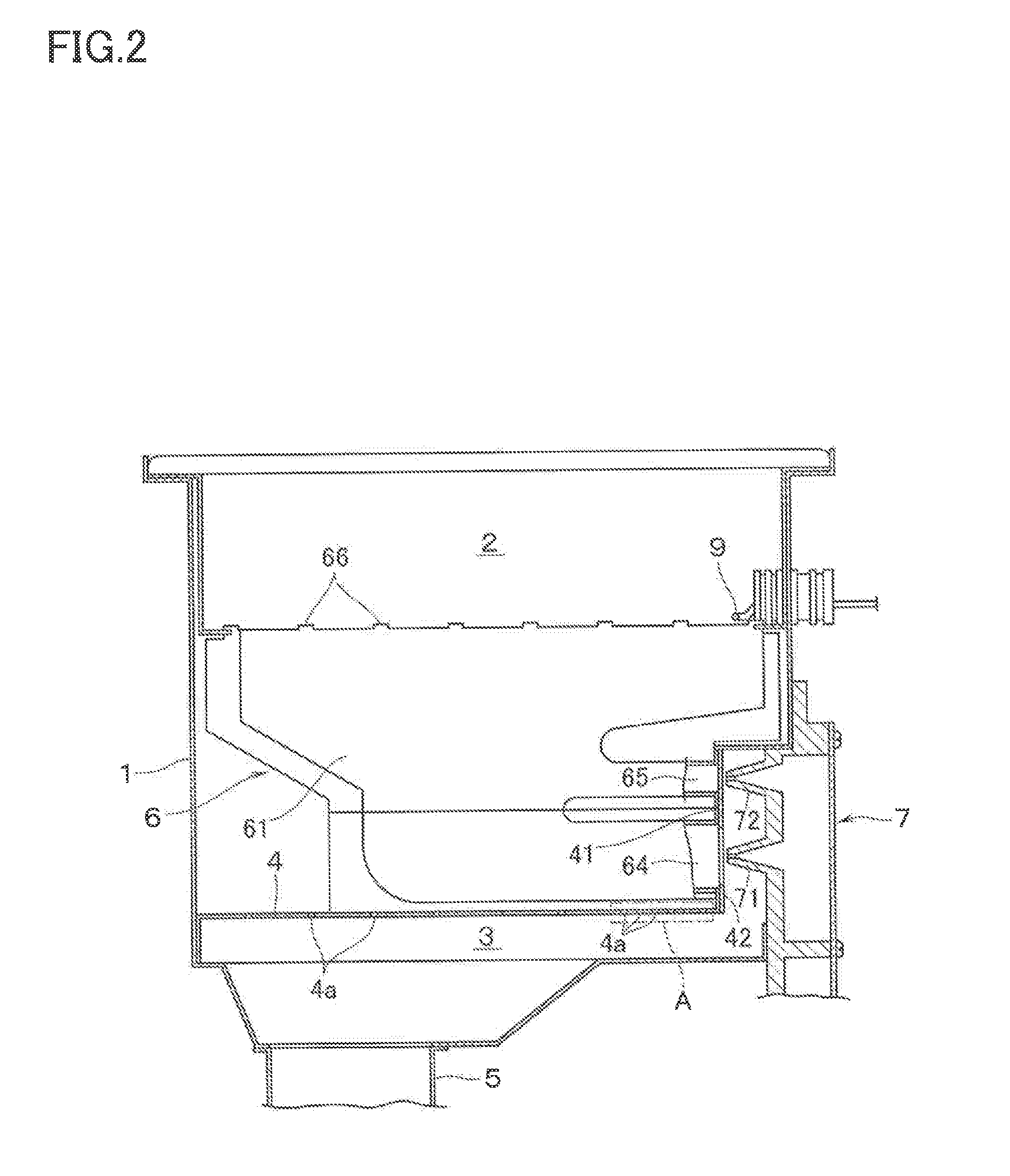
[0020]With reference to FIGS. 1 and 2, the combustion apparatus of the present embodiment includes a combustion housing 1. The upper surface of the combustion housing 1 is opened, and a heating object (not illustrated) such as a heat exchanger is placed on the combustion housing 1.

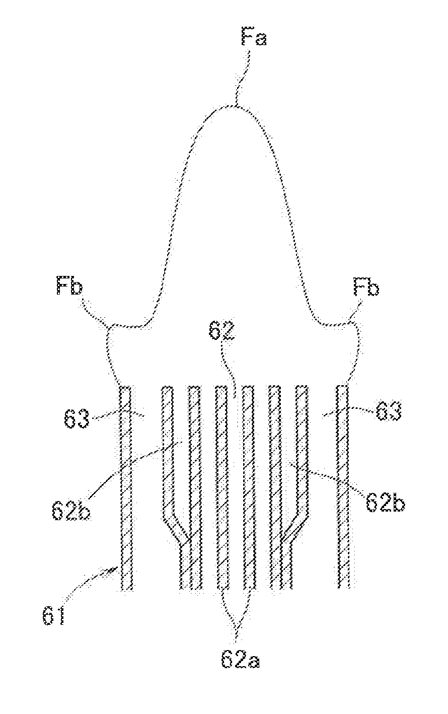
[0021]A partition plate 4 partitioning the space in the combustion housing 1 into a combustion chamber 2 and an air supply chamber 3 on the lower side of the combustion chamber 2 is provided in the combustion housing 1. A combustion fan (not illustrated) is connected to the bottom face of the air supply chamber 3 with a duct 5 put between them, and air is supplied from the combustion fan to the air supply chamber 3. A multiplicity of distributed holes 4a are formed in the partition plate 4 at the positions corresponding to the arrangement pitch portions of rich-lean burners 6, which will be described later. Then, th...


PUM


Abstract

A combustion apparatus has: a combustion housing; a partition plate provided in the combustion housing to partition a space in the combustion housing into a combustion chamber and an air supply chamber; and a plurality of rich-lean burners arranged in a right-left direction of the combustion chamber. A multiplicity of distributed holes are formed in the partition plate through which distributed holes secondary air is supplied from the air supply chamber to the combustion chamber. A flame rod facing to an upper side of a part of the rich-lean burners stops combustion when the flame rod does not detect any flames owing to a flame lift at a time of an oxygen deficiency. A supply quantity of the secondary air to the part of the rich-lean burners to which part the flame rod faces is larger than those to other parts.

Description

BACKGROUND OF THE INVENTION[0001]This application claims priority under 35 U.S.C. §119 to Japanese Patent Application No. 2010-127852, filed Jun. 3, 2010, which is incorporated by reference.FIELD OF THE INVENTION[0002]The present invention relates to a combustion apparatus equipped with a rich-lean burner and a flame rod for combustion stopping at the time of an oxygen deficiency.DESCRIPTION OF THE RELATED ART[0003]The following combustion apparatus has conventionally been known (see, for example, Japanese Patent Application Laid-Open Publication No. 2006-266516). That is, the combustion apparatus includes a combustion housing and a partition plate provided in the combustion housing to partition the space in the combustion housing into a combustion chamber and an air supply chamber on the lower side of the combustion chamber. The combustion apparatus further includes a plurality of rich-lean burners arranged in the right-left direction of the combustion chamber, and the combustion a...

Claims


Application Information

Patent Timeline
IPC IPC(8): F23L9/06F23D14/00F23H1/02
CPCF23C2201/20F23C2900/06041F23D14/583F23D14/105F23D14/045
Inventor SHIMIZU, MASAKAZU
Owner RINNAI CORP
Why Eureka
Try Eureka