Apparatus for aligned supply of fastening parts

a technology for fastening parts and accessories, applied in the direction of screwdrivers, metal-working equipment, wrenches, etc., can solve the problems of limited supply capacity, difficult assembling into automatic assembly machines, increased overall height of the apparatus, etc., to suppress the overall height of the entire apparatus, accurately rotate and displaced, and enhance the effect of supply capacity

Active Publication Date: 2011-12-08
QP FASTENING WORKS CO LTD
View PDF5 Cites 13 Cited by
  • Summary
  • Abstract
  • Description
  • Claims
  • Application Information

AI Technical Summary

Benefits of technology

According to the present invention, in a position of a lateral direction with the shaft part leading end forward, and the head part behind, the fastening parts supplied through the supply passage are rotated and displaced, and at a lower position of the pressing punch, the rotary holding claw body for positioning and holding coaxially with the pressing punch is disposed closely to the lower position of the pressing punch, and is rotated and displaced by a specific angle about the axial line, and the essential parts of the apparatus for displacing and supplying the fastening parts from a position in a lateral direction to a position in a longitudinal direction can be composed in a very compact design. At the lower position of the pressing punch, the fastening parts can be positioned and held promptly and accurately, so that the supply capacity may be enhanced.
According to claim 2 of the invention, the slide guide assembled in the punch holder for mounting the pressing punch movably up and down by way of the guide post is provided with the rotary holding claw body and the supply passage, and the entire apparatus can be designed in a compact structure while suppressing the overall height of the entire apparatus.
According to claim 3 of the invention, the head part of the fastening parts gripped and held by the both disk-shaped gripping claws of the rotary holding claw body is pressed by the pressing punch, and the both disk-shaped gripping claws are pushed and opened, and in this state when pushing and sending out the fastening parts from the space between the both disk-shaped gripping claws, the stopper piece fitted freely and movably along the both stopper receiving concave parts blocks the front end opening of the supply passage, and the shaft part of the fastening parts to be supplied next will not invade into the expanded space between the both disk-shaped gripping claws, and the fastening parts can be supplied sequentially by separate each one securely.
According to claim 4 of the invention, when the stopping pins are engaged with the cut-off parts provided in the both flange parts of the both disk-shaped gripping claws, the both disk-shaped gripping claws can be accurately rotated and displaced by a specific angle.
According to claim 5 of the invention, when the fastening parts are inserted into the space between the both disk-shaped gripping claws from the supply passage, since the outward move of the both disk-shaped gripping claws is arrested by the stopper pins, the both disk-shaped gripping claws are prevented from being pushed and expanded by the head part of the fastening parts, and on the other hand, when the both disk-shaped gripping claws gripping the fastening parts are rotated and displaced by a specific angle and the stopper pins are opposite to the cut-off parts provided in the flanges parts, outward move of the both disk-shaped gripping claws is allowed, and when the head part is pressed by the pressing punch, the both disk-shaped gripping claws are pushed and expanded by resisting the push springs, so that there is no problem in rotation, displacement or supply of fastening parts.

Problems solved by technology

In a conventional apparatus for aligned supply of fastening parts of this type for aligning fastening parts in a longitudinal direction so that the shaft part is positioned in a vertical direction, and supplying coaxially at a lower position of a pressing punch or bit (extruding bar) of an automatic assembling machine, the overall height of the apparatus is increased, and in particular where the shaft part is too long, it may be difficult to assemble into the automatic assembling machine.
The apparatus for aligned supply disclosed in patent literature 1 can be lowered in the overall height of the apparatus, but requires two actions for inverting and transferring, and moving horizontally (moving laterally) the gripping claw of the fastening parts, and is hence limited in the supply capacity.
Especially in the case of fastening parts longer in the shaft pat, there is a risk of contacting with the pressing punch when inverting and transferring the fastening parts by the gripping claw, and it was necessary to modify the layout of the gripping claw or change the entire apparatus configuration.

Method used


Image

  • Apparatus for aligned supply of fastening parts
  • Apparatus for aligned supply of fastening parts
  • Apparatus for aligned supply of fastening parts

Examples


Embodiment Construction

A preferred embodiment of the present invention is described specifically below by referring to the accompanying drawings.

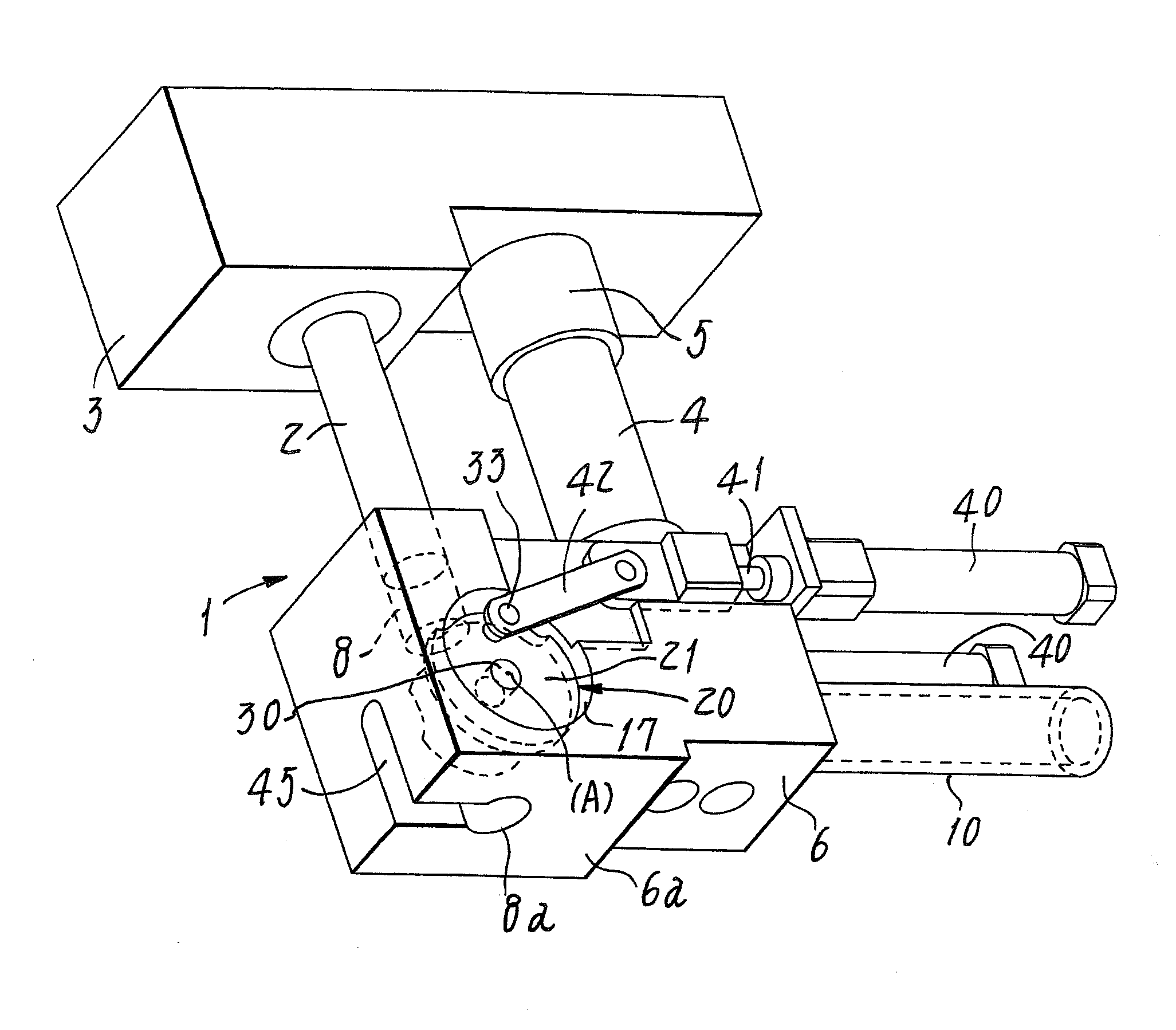
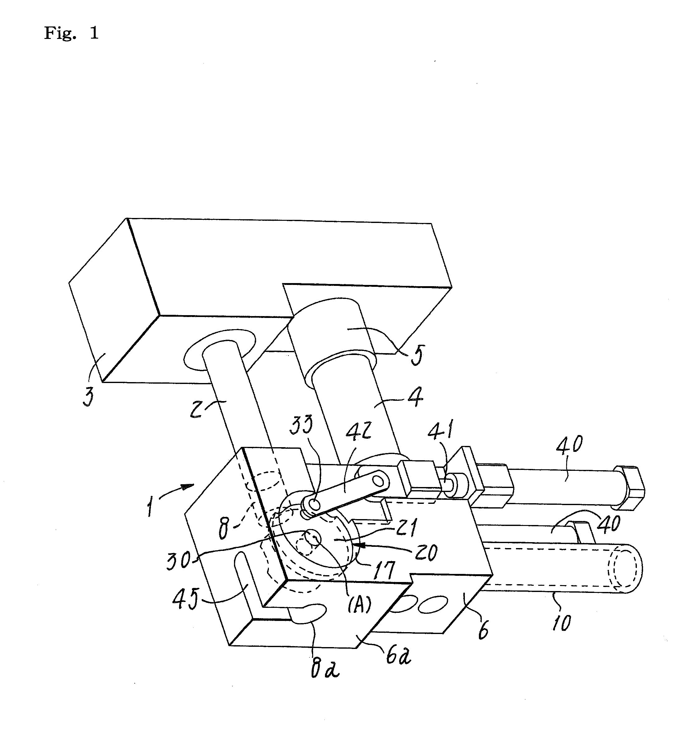
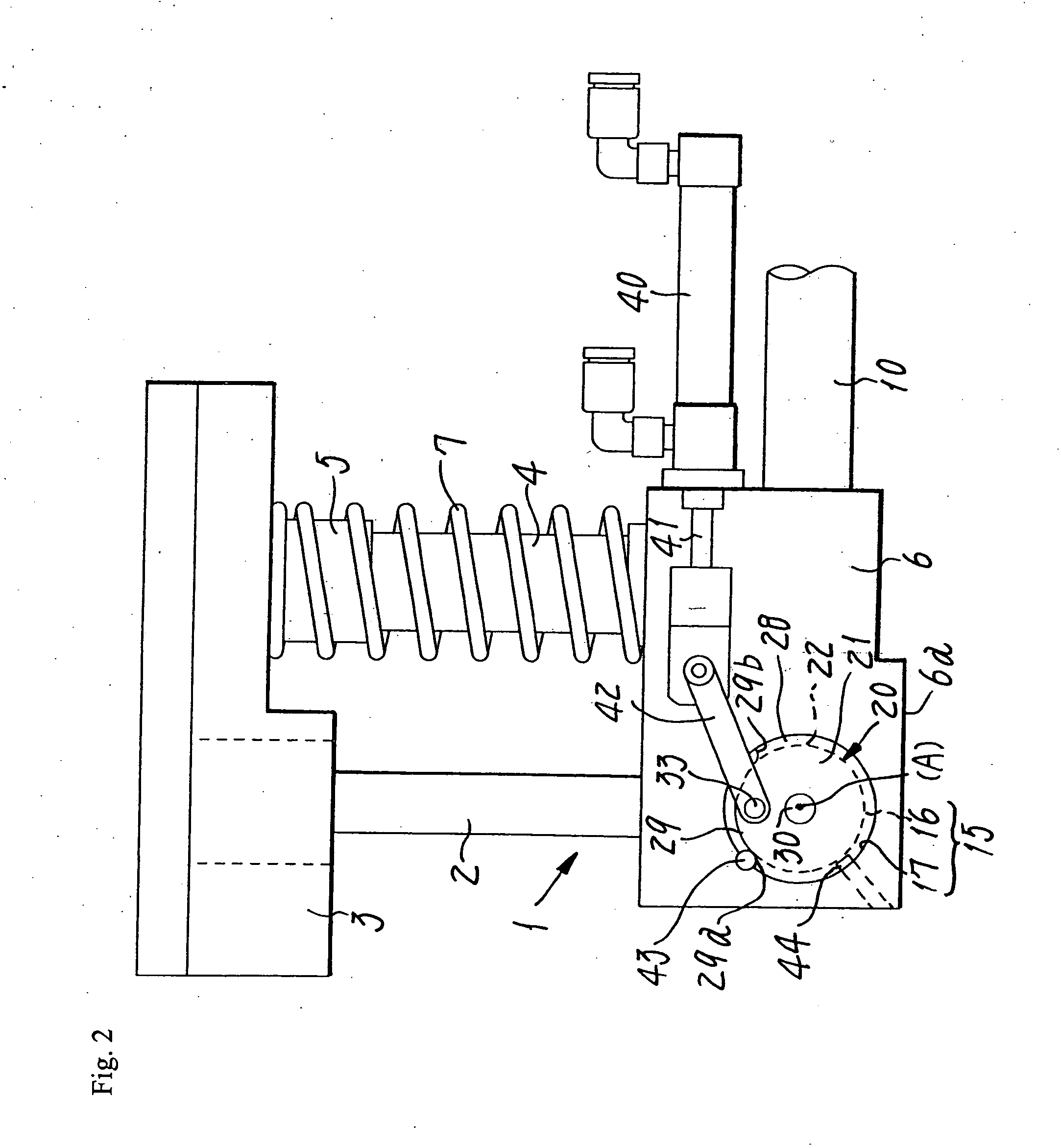
The drawing shows a preferred embodiment of an apparatus for aligned supply of fastening parts of the present invention applied to an automatic crimping machine for aligning and supplying clinch bolts 11 (see FIG. 3), and affixing on a metallic panel 51 (see FIG. 6). The apparatus 1 for aligned supply shown in FIG. 1 is mounted on a ram of a press (not shown) of an automatic crimping machine, and is used at a position opposite to a crimping die 50 (see FIG. 6) of the press.

FIG. 1 to FIG. 3 show a state of a rotary holding claw body 20 (described below) for composing a principal part of the apparatus 1 for aligned supply of the present invention, at a waiting position before rotation and displacing by gripping the clinch bolts 11 as fastening parts. The apparatus 1 for aligned supply has a pressing punch 2, and a punch holder 3 for mounting the pressing punch 2 is...


PUM

PropertyMeasurementUnit
specific angleaaaaaaaaaa
inclination angleaaaaaaaaaa
diameteraaaaaaaaaa

Abstract

An apparatus for aligned supply of fastening parts into an automatic assembling machine includes a rotary holding claw body, disposed at a lower position of a pressing punch, for gripping the fastening parts supplied in a position of a lateral direction by way of a supply passage, by passing through an intersection of an axial line of the pressing punch and an axial line of the supply passage, and rotating and displacing by a specific angle about a lateral axial line orthogonal to the both axial lines, and positioning and holding the fastening parts coaxially with the pressing punch at a lower position of the pressing punch. The rotary holding claw body has a pair of mutually opposing disk-shaped gripping claws, and the both disk-shaped gripping claws are forced to as to press push springs each other, and the fastening parts are gripped by the both disk-shaped gripping claws.

Description

TECHNICAL FIELDThe present invention relates to an apparatus for aligned supply of fastening parts for supplying clinch bolts, headed screws, rivets, pins, and other various fastening parts having a head at one end of a shaft part, to an automatic assembling machine, for example, automatic crimping machine of clinch bolt, or automatic screwing machine of headed screw.BACKGROUND ART In a conventional apparatus for aligned supply of fastening parts of this type for aligning fastening parts in a longitudinal direction so that the shaft part is positioned in a vertical direction, and supplying coaxially at a lower position of a pressing punch or bit (extruding bar) of an automatic assembling machine, the overall height of the apparatus is increased, and in particular where the shaft part is too long, it may be difficult to assemble into the automatic assembling machine.To solve such problems, an apparatus for aligned supply of fastening parts is disclosed in Patent Publication No. 33006...

Claims


Application Information

Patent Timeline
Patent Type & Authority Applications(United States)
IPC IPC(8): B23P19/06
CPCY10T29/5343B23P19/006B25B23/10B23P19/062B25B23/04
Inventor SHINJO, HIROSHI
Owner QP FASTENING WORKS CO LTD
Why Eureka
Try Eureka