Sheets formatted for use in binding machines

a technology of binding machine and sheets, applied in the field of sheets, can solve the problems of difficulty in adhesion of adhesives to the surface, sheet is typically not bound, other difficulties in bookbinding, etc., and achieve the effects of reducing the thickness of sheets, increasing the surface area for adhesion, and improving the bind quality

Inactive Publication Date: 2011-12-08
HOCKING HAROLD P
View PDF2 Cites 5 Cited by
  • Summary
  • Abstract
  • Description
  • Claims
  • Application Information

AI Technical Summary

Benefits of technology

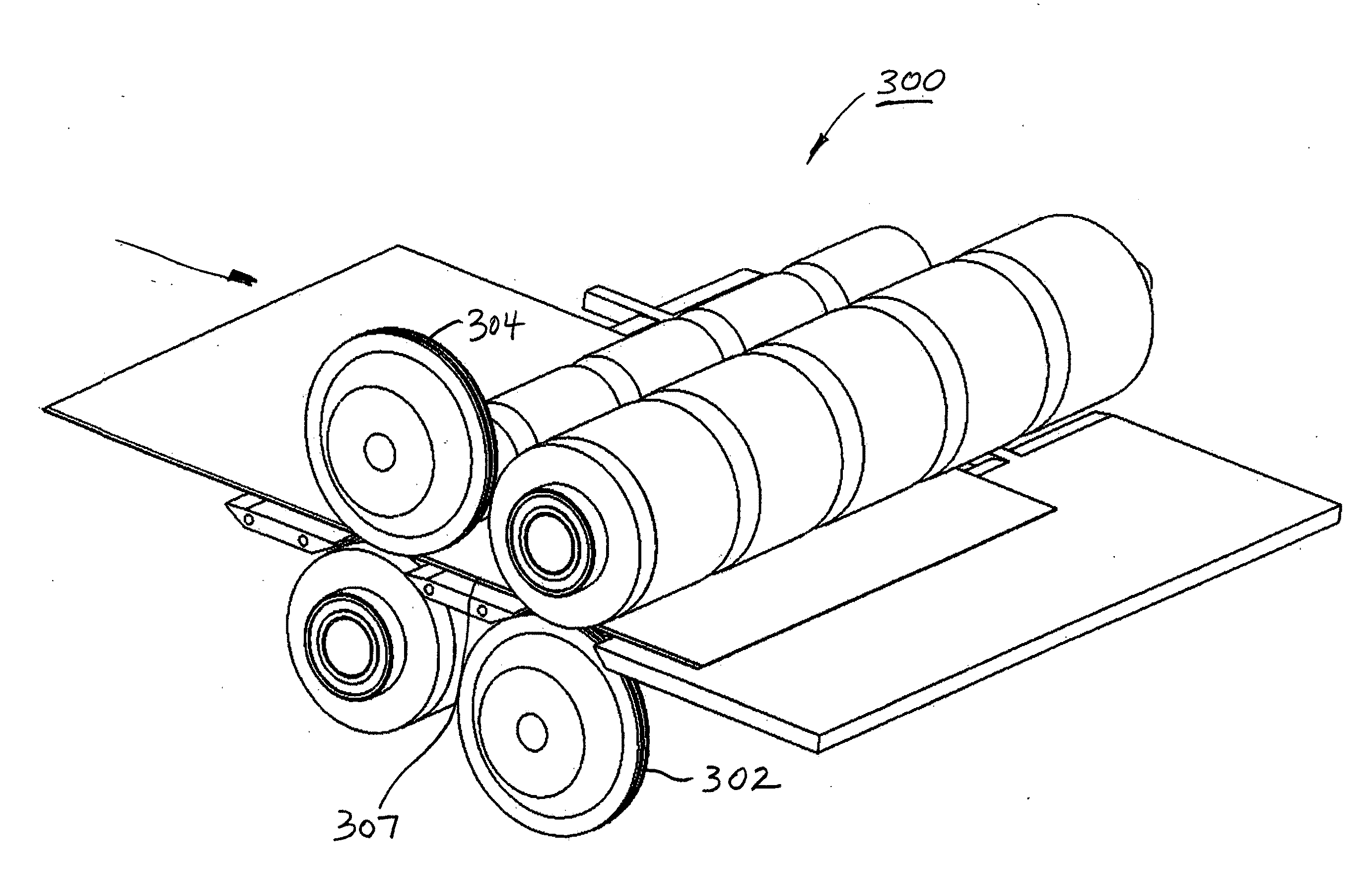
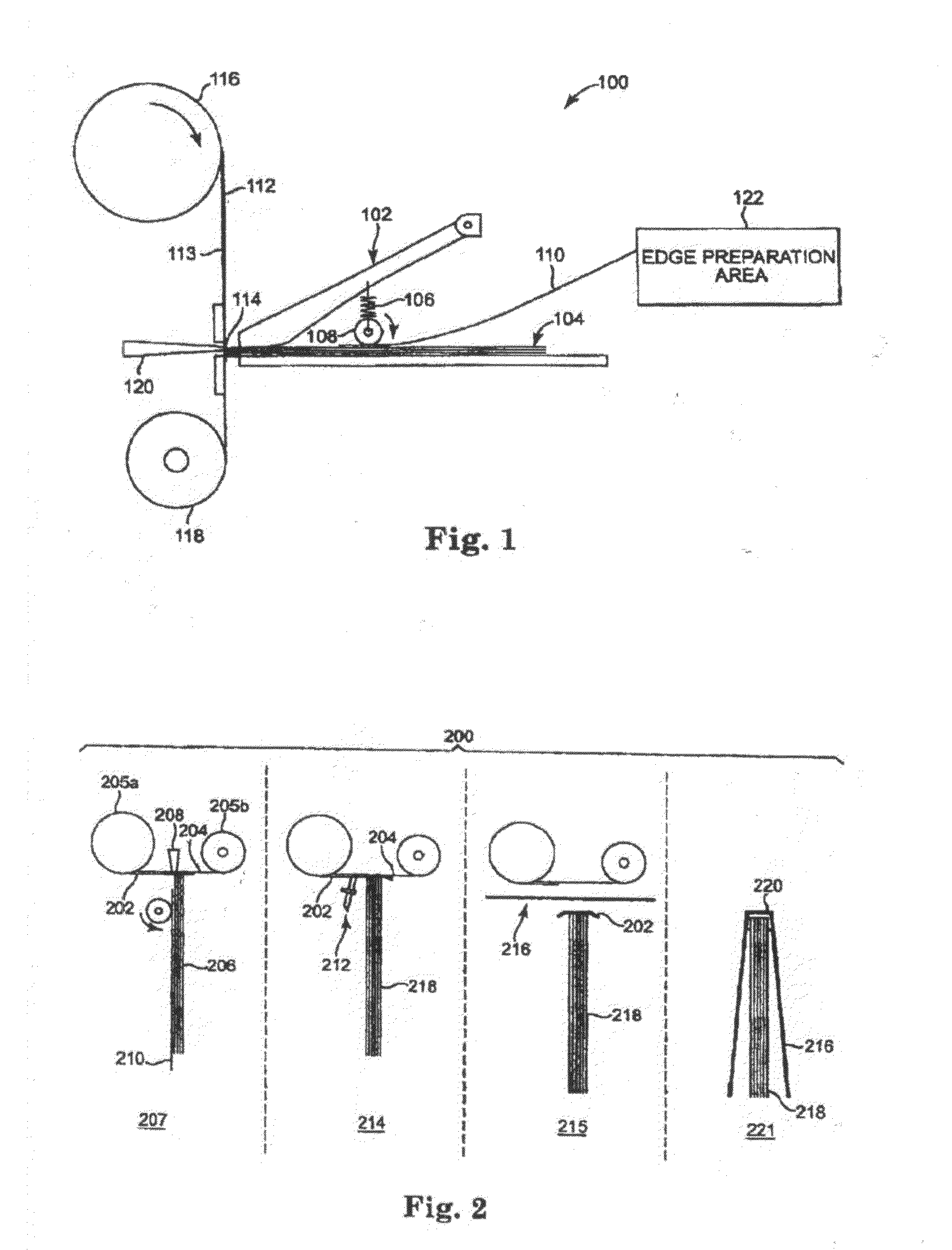
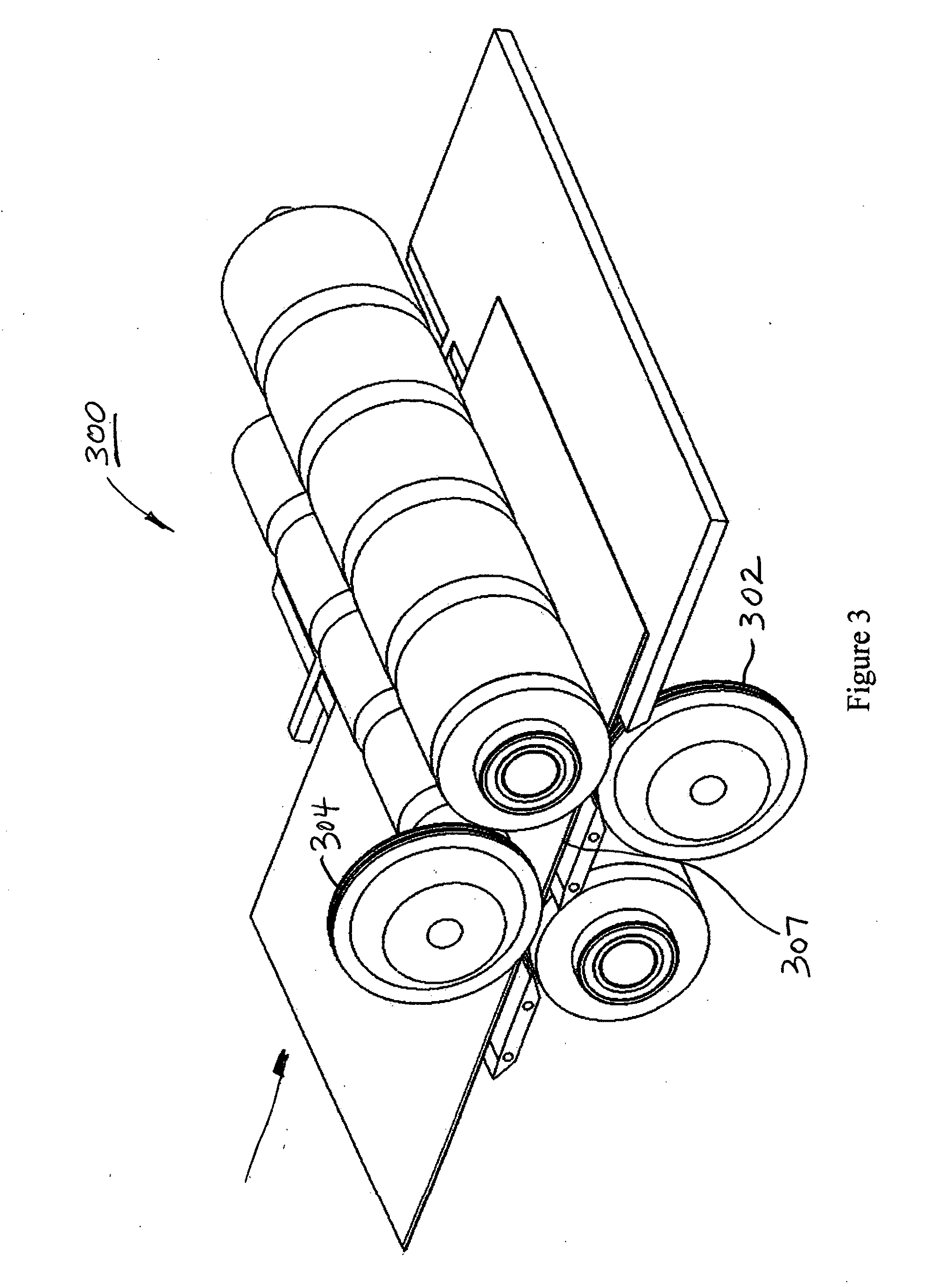
[0009]By grinding or abrading off undesirable coatings from the top layer on one or both sides of the sheet to a depth of approximately 2- to 3-mils along the spine edge of the sheets to be bound enhances the bind quality by allowing the adhesive to flow around the sheet edges during the bookbinding process. Rather than relying on the adhesive to bond only to the edge of the sheet, the surface area for adhesion is greatly increased.
[0010]Another advantage to the preconditioning process described hereinabove is that the thickness of the sheets are reduced along the spine or bound edge resulting in reduced stress along the bound edge of each sheet. Another variable is the width of the reduced section along the bound edge. If this edge is two or three thicknesses of the original sheet, (˜30-mils) then the adhesion is increased and the stress on the joint is reduced, although the sheets tend not to lay flat. If the formatting is performed on a wider section, (120-mils) then the sheets are able to bend over a significantly larger area. The benefit is reduced stress along the spine joint and a significant advantage in the ability of the photo-book to lay flat when opened.
[0012]Conditioning, or formatting, the sheets by removing the material from one side of the paper edge creates a step on one side only. Sheets formatted in this manner would also create a gap between the sheets when gathered together to create a book block allowing the adhesive to migrate between the sheets during the thermal bookbinding process.
[0015]The present invention thus provides paper sheets that are formatted on their edges in a manner such that the adhesive used in bookbinding systems provides an increased adhesion surface and reduces stress along the spine or bound edge of the resultant photo-book while increasing sheet flexibility.

Problems solved by technology

Although the coatings, while enhancing the surface to be printed on, make it difficult for adhesives to adhere to the surface thus creating a problem when binding the edge of the paper using thermal activated adhesives.
As a result, these sheets are typically not bound in the conventional method of bookbinding.
In addition to the difficulty with the coatings on the surface of the sheets hampering the adhesion during the thermal bookbinding process as noted hereinabove, the sheets are typically thicker than normal 20-pound bond, 4-mil thick paper sheet.
The added thickness from 4-mils to 10- to 12-mils, while enhancing the feel of the photo-book page, creates some other difficulties with regard to bookbinding.
In addition the sheets are not as flexible and do not tend to lay flat when the book is opened.
Although the prior art discloses various techniques to increase sheet binding strength, the sheet edge typically requires additional processing after printing with the attendant increase in costs.

Method used


Image

  • Sheets formatted for use in binding machines
  • Sheets formatted for use in binding machines
  • Sheets formatted for use in binding machines

Examples


second embodiment

[0050]FIG. 6 shows the present invention wherein the material is removed from sheet 320 in a manner creating a step 321 having a single surface 322 formed by an abrading step.

[0051]FIG. 7 illustrates a book block of sheets 320 ready for binding, the gaps 324 between sheets 320 allowing adhesive to migrate between the sheets during the thermal bookbinding process.

third embodiment

[0052]FIG. 8 shows the present invention wherein the functions of enhancing the binding adhesion is separated from the function of the added flexibility of the sheet in the vicinity of the spine. A portion 342 of the sheet 340 separating the two sheet zones (344,346) retains the thickness of the sheet 340 (not thinned down) thereby blocking adhesive from flowing too far in between the sheets which can result in inconsistencies in the bind. Zone or hinge area 346 thus provides sheet flexibility after sheets 340 are formed in a book as shown in FIG. 9. This enables the book sheets to return to its original position after being bent or otherwise moved (i.e. after a user of the book, such as an album, flips the bound sheet for viewing and then releases the sheet).

[0053]The typical dimensions of sheet 340 are as follows:[0054]Sheet 340 thickness: 12 mils[0055]Section 346: thickness 4-6 mils, width 1 / 16″-¼″[0056]Section 342: thickness 12 mils, width 20 mils-50 mils[0057]Section 344: thick...

fourth embodiment

[0059]FIG. 10 shows the present invention wherein the transition edge 354 from sheet 360 to the hinge area 346 is tapered.

[0060]For the stress in a sheet of paper being bent as the sheets, bound to the spine (similar to a beam being bent), the following provides an analysis of the forces involved.

[0061]Referring to FIGS. 15(a) and 15(b), stress(s) in a cantilever beam (beam supported on only one end) is equal to the bending moment (M) times the distance from the neutral axis to the outermost fiber (c) divided by the moment of inertia of the beam (I).

S=Mc / I; M=Fd; I=bh3 / 12

[0062]If the thickness of the paper (represented by the variable h) varies form 4-mils to 12-mils, the stiffness represented by the moment of inertia (I) will increase by 27 times, everything else being the same. The stress when the sheet of paper corresponding to a (beam) is attached to the spine by the adhesive (and assuming that the only variable to change is the thickness of the sheet of paper (h)):

S(4-mil paper...


PUM


Abstract

Sheets for use in a binding apparatus, the sheets being conditioned by removing the outer layer of the sheet on one or both surfaces along the sheet edge that will be bound.

Description

BACKGROUND OF THE INVENTION[0001]1. Field of the Invention[0002]The present invention is directed to sheets that have been formatted for use with a binding machine.[0003]2. Description of the Prior Art[0004]Typically papers used to print high resolution digital photos used as pages in a photo album or photo book are coated with materials and coatings to enhance the detail of these pictures. These materials and coatings consist of clay or silicate solutions that are proprietary to the paper manufacturing companies. Although the coatings, while enhancing the surface to be printed on, make it difficult for adhesives to adhere to the surface thus creating a problem when binding the edge of the paper using thermal activated adhesives. As a result, these sheets are typically not bound in the conventional method of bookbinding. In order to bind these sheets, they are typically stapled or crimped together prior to applying a cover to the book or photo-book. Other methods have been employed ...

Claims


Application Information

Patent Timeline
Patent Type & Authority Applications(United States)
IPC IPC(8): B42D1/00B42C19/00
CPCB42C19/00
Inventor HOCKING, HAROLD P.
Owner HOCKING HAROLD P
Why Eureka
Try Eureka