
Electric Motors

Active Publication Date: 2011-12-08
CONNECTING PRODS
View PDF7 Cites 1 Cited by
  • Summary
  • Abstract
  • Description
  • Claims
  • Application Information

AI Technical Summary

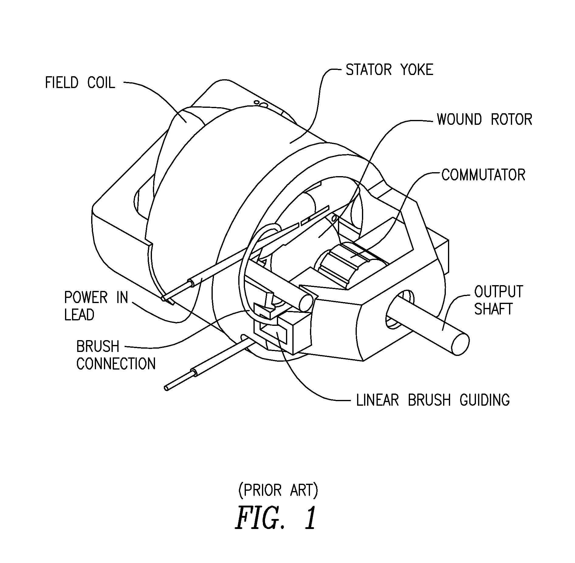
Benefits of technology

[0011]The present inventor has found that if an “off the shelfuniversal motor is connected to power directly to the brushes circumventing the field coils, the motor turns strongly in the opposite direction to which it was designed. Without being confined to a single theory, the inventor deduced from this experiment that there are two turning forces developed in the universal motor, one being positive from the point of view of the intended action, and the other being negative. Obviously, the positive force is stronger, but although the addition of the positive and the negative force gives the resultant intended force, it is possible for the negative force to be equal or greater than the resultant force but in the opposite direction. So, if the positive force is eliminated, then the negative force alone could produce a stronger motor which turns in the opposite direction and be more efficient.
[0015]While this embodiment is similar in construction to the stepping motor, the variable reluctance motor and the switched reluctance motor, in operation, it, like the other embodiments disclosed herein, maintains the condition of torque producing high reluctance and eliminates the pulsations of amperage and torque which are evident in prior art reluctance motors, with no need for costly electronic control.

Problems solved by technology

No other design has yet as effectively satisfied the special niche need for high speed, variable speed and low cost in small appliances as has the “universal” motor.
This is termed “rotor reaction” and is considered a detriment to efficient motor action.
This requires an arrangement which is costly, fragile and subject to breakage and is difficult to service.
These motors have advantages of low cost through the elimination of unnecessary copper but have severe disadvantages of torque variation (ripple) and acoustic noise which, so far, is only partly mitigated by expensive tailored electronically controlled drives.

Method used


Image

  • Electric Motors
  • Electric Motors
  • Electric Motors

Examples


first embodiment

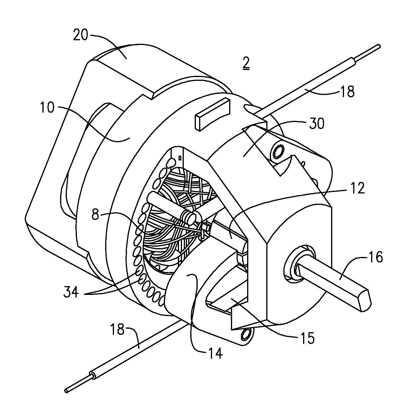
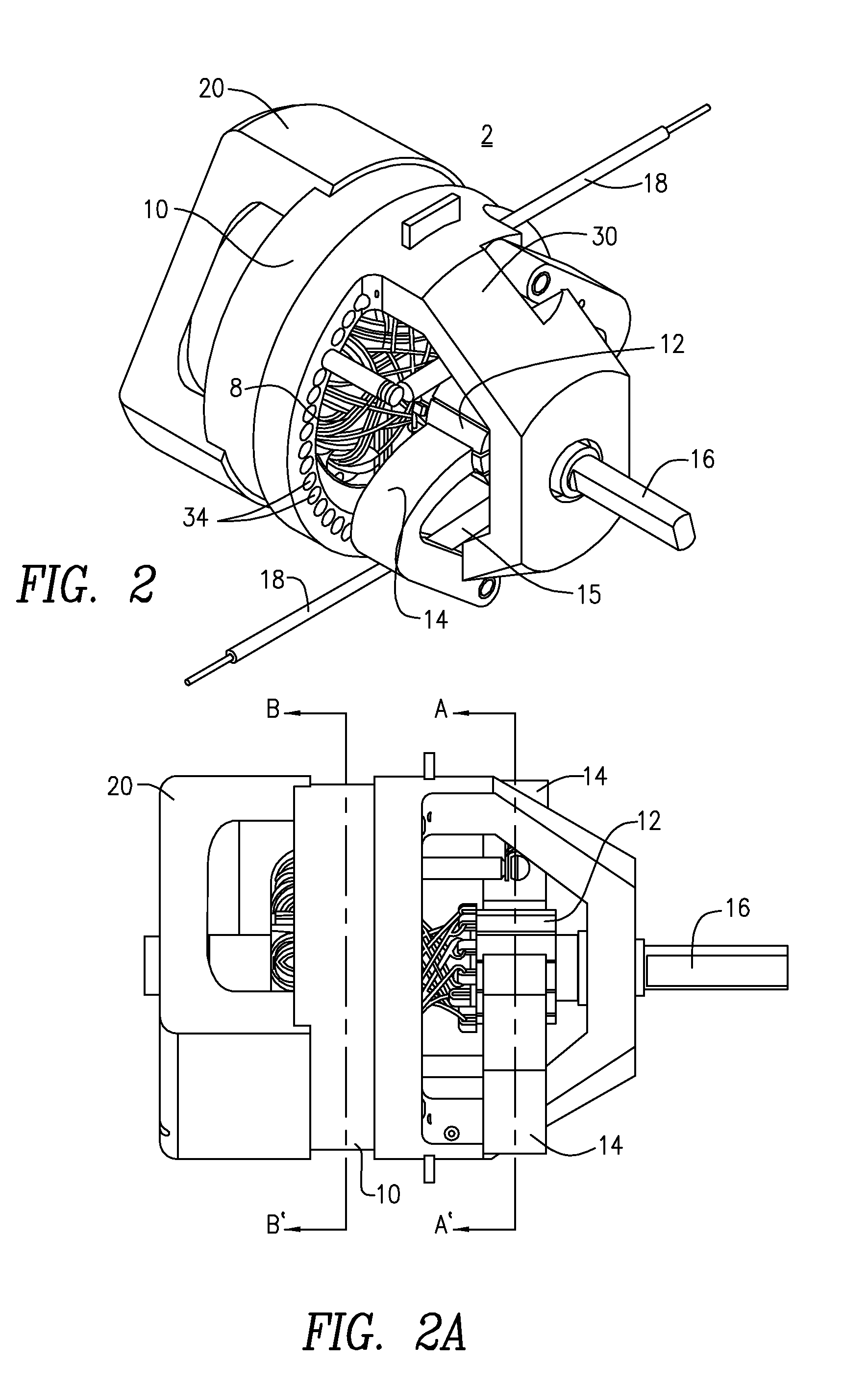
[0040]Now referring to FIGS. 2, 2A, 2B and 2C, in accordance with the present disclosure, an electric motor 2 is disclosed wherein stator field coils / magnets are eliminated and the rotor coils are the only means of excitation of the magnetic field. As shown in FIGS. 2-2C, the electric motor includes rotor core 4 with slots 6, rotor coils 8 wound around and through the slots 6 in the rotor core 4, stator ring 10, commutator 12, brush 14, output shaft 16 and power in leads 18. Motor 2 may include rear bearing bell 20 and bearing mount 30. A brush spring 15 may be employed, discussed further hereinbelow. A small air gap 40 separates the rotor and the stator ring 10 surrounding it. The air gap 40 may be from about 0.008″ to about 0.025″. The coils 8 are wound and connected to the commutator 12 in a manner that induces many superimposed flux fields. The resultant flux from all the energized coils flows diametrically through the rotor core 4, and therefore can be misaligned with the pole ...

second embodiment

[0045]Now referring to FIGS. 3-3C in a second embodiment a motor 100 is disclosed which has the same principal of operation with the same relationship between stator and rotor components as the motor shown in FIG. 2, but is constructed differently. Rotor 102 has two coil banks 108a and 108b, stator elements which conduct the magnetic circuit are two stator bars 110a and 110b, parallel to the axis of the motor 100, connecting the motor bearing brackets 106a and 106b, commutator 112, brush 114, optionally spring 115, output shaft 116 and leads 118. In accordance with this embodiment, without being confined to a single theory of operation, the principle of the motor 100 (without field coils) is to produce torque by displacing part of the magnetic circuit so that nature is always trying to align the magnetic circuit, as in a compass, and the longitudinal length of the conductors in the coils windings is not a factor. But it is now essential to have coils to create a magnetic field, and ...


PUM


Abstract

Electric motors are disclosed with coils which induce a magnetic flux field which by its relationship with ferromagnetic poles provide the motoring force without use of an auxiliary magnetic field. The motors may be employed with fixed or pivotably mounted brushes. Pivotable brushes for electric motor brushes are disclosed.

Description

CROSS-REFERENCE TO RELATED APPLICATIONS[0001]This application claims the benefit of U.S. Provisional Patent application Ser. Nos. 61 / 352,578, filed Jun. 8, 2010 and 61 / 353,473 filed Jun. 10, 2010, the disclosures of which are incorporated in their entirety by reference herein.FIELD OF THE INVENTION[0002]The invention relates to the field of electric motors. More specifically, it relates to simplified, low cost, compact, high power, easily reversed, easily maintained electric motors with coils which induce a magnetic flux field which by its relationship with ferromagnetic poles provide the motoring force.BACKGROUND OF THE INVENTION[0003]A “universal” prior art motor, such as is shown in FIG. 1, is an electric series wound motor which can run on AC or DC power. Such motors are small, frequently connected directly to standard 110 volt AC power and run at high speed. They are generally employed in hand-held and counter top appliances such as mixers, hand drills, vacuum cleaners and in g...

Claims


Application Information

Patent Timeline
IPC IPC(8): H02K37/04
CPCH02K5/146H02K5/225H02K23/40H02K23/36H02K27/00H02K23/18
Inventor FREAKES, ANTHONY
Owner CONNECTING PRODS
Learn More