Wall-mounted sliding storage enclosure with fail-safe position fixing mechanism

a technology of fixing mechanism and sliding storage enclosure, which is applied in the field of storage enclosures, can solve the problems of heavy, bulky, complicated mechanisms, etc., and achieve the effects of convenient use, simple construction, and economical manufactur

Inactive Publication Date: 2011-12-08
STONE PETER
View PDF17 Cites 6 Cited by
  • Summary
  • Abstract
  • Description
  • Claims
  • Application Information

AI Technical Summary

Benefits of technology

[0007]It is another object of the invention to provide a wall-mounted sliding storage system that is a simple in construction and economical to manufacture.
[0009]It is yet another object of the invention to provide a wall-mounted sliding storage system, as in the previous object that utilizes few mechanical components to render the system reliable.
[0010]It is a further object of the invention to provide a wall-mounted sliding storage system as in the previous objects that includes a simple and reliable mechanism for reliably fixing the position of the cabinets at any desired height.
[0011]It is a further object of the invention to provide a system as in the previous object a motion-arresting mechanism that is failsafe and automatically prevents the cabinets from dropping or freely falling even when the user inadvertently releases a movement-actuating mechanism on the cabinets.
[0013]It is yet a further object of the invention to provide a wall-mounted sliding storage system of the type under discussion that is simple to assemble and install by an end-user.

Problems solved by technology

The known movable storage cabinets, however, have typically been bulky, heavy and required complicated mechanisms for raising and lowering the cabinets and to ensure that the cabinets can be used safely.

Method used


Image

  • Wall-mounted sliding storage enclosure with fail-safe position fixing mechanism
  • Wall-mounted sliding storage enclosure with fail-safe position fixing mechanism
  • Wall-mounted sliding storage enclosure with fail-safe position fixing mechanism

Examples


Embodiment Construction

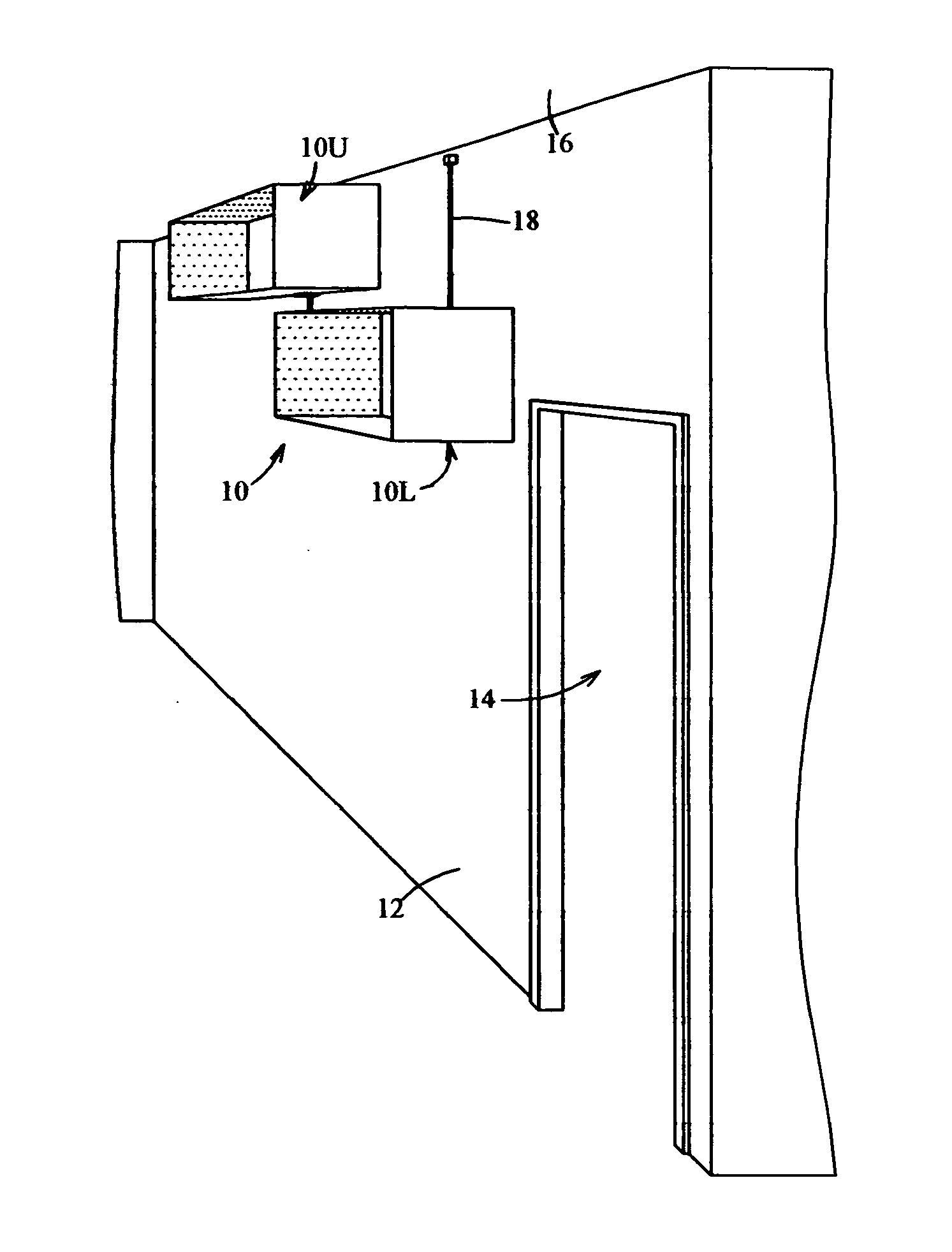
[0037]Referring now specifically to the Figures, in which identical or similar parts will be designated by the same reference numerals throughout, and first referring to FIG. 1, the cabinets, in accordance with the present invention are generally designated by the reference numeral 10.

[0038]The cabinets 10 are shown mounted on a wall 12 with a door 14. The ceiling is designated by the reference 16. If the frame of the door 14 has a height corresponding to a standard height for such openings the movable cabinets 10 are intended to be a slidably movable, as to be more fully described below, between an upper position against or proximate to the ceiling 16 to a lowered position generally coextensive with the height upper end of the frame of the door. However, the cabinets can to be mounted for movements to a position below upper horizontal portion of the doorframe, with different degrees of advantage. It will be appreciated that one of the cabinet 10 is shown in its uppermost position w...


PUM


Abstract

A sliding storage system includes a vertical rod having upper and lower ends. Brackets attach the upper and lower ends of the rod to a wall to fix the rod in a vertical orientation.A storage device in the form of a rigid cabinet slidably is mounted on the rod for free sliding movements between (i) the lower end of the rod for positioning the storage device in a lower position to provide access to a user and allow the user to place an object on or remove an object from the cabinet and (ii) the upper end for positioning the storage device in a storage position generally above the living space of the user. A locking member in the form of a clutch plate cooperates with the cabinet and the vertical rod, the clutch plate being movable between a locking position for locking the cabinet against vertical movements along said rod and a releasing position enabling the cabinet to selectively and freely move vertically upwardly and downwardly along the rod. A spring acting between the cabinet and the clutch plate normally urges the clutch plate to move to the locking position. A manual release is actuatable directly by a user or indirectly by a line extending over a sheave above the rod to move the clutch plate from a locking position to a releasing position when manually actuated by a user to overcome the action of the spring. In this way, manual activation of the manual release allows a user to selectively raise or lower the cabinet to place an object on or remove an object from the cabinet in a lowered position and to store an object in a raised position of the cabinet.

Description

BACKGROUND OF THE INVENTION[0001]1. Field of the Invention[0002]The invention generally relates to storage enclosures mounted for vertical movements and more specifically to a wall-mounted sliding storage enclosure with a fail-safe position fixing mechanism.[0003]2. Description of the Prior Art[0004]Storage cabinets and like enclosures have been known that are designed to move between a lower position providing a user with access to the enclosures for placing items into or removing items from the enclosures and an upper position closer to the ceiling that utilize space that is normally not used. As such extra storage can be used for storing seasonal items, such as winter clothing in the summer and summer clothing in the winter. Seldom used items such as books, serving pieces and the like can also be conveniently stored in such cabinets that do not take up valuable space or interfere with the movements of occupants or other objects that must be maintained at the floor level, such as ...

Claims


Application Information

Patent Timeline
Patent Type & Authority Applications(United States)
IPC IPC(8): A47B51/00A47B96/06A47B57/06
CPCA47B43/006A47B51/00
Inventor STONE, PETER
Owner STONE PETER
Why Eureka
Try Eureka