Clock signal generator

a clock signal and generator technology, applied in the direction of generating/distributing signals, pulse techniques, instruments, etc., can solve the problems of circuit design redesigns or additional costs, emi can be difficult to understand and correct,

Active Publication Date: 2011-12-08
NXP BV
View PDF0 Cites 6 Cited by
  • Summary
  • Abstract
  • Description
  • Claims
  • Application Information

AI Technical Summary

Benefits of technology

[0012]Utilising a plurality of frequency division factors can ensure that any electromagnetic interference (EMI) is spread out over a range of frequency values, and not concentrated on a single clock frequency. Providing a controller that periodically replaces an in-use frequency division factor with another frequency division factor can be considered as a convenient implementation of achieving the clock frequency spread. For example, further oscillators may not be required to provide the control of the main oscillator, and this can reduce the silicon area / real-estate that is required by the clock signal generator. Furthermore, in some examples having a clock signal and an oscillator signal available at different frequencies can be advantageous as control signals can be available at different frequencies.
[0030]The clock signal generator may be configured to receive only one oscillating signal. This can reduce the number of components that are required when compared with the prior art, and this can provide for a reduction in required silicon area. There is also provided a system comprising:

Problems solved by technology

Electromagnetic interference (EMI) emissions from power supplies are an important problem and are often the cause of redesigns or additional costs in circuit design.
This can be important as EMI can be difficult to understand and correct.

Method used


Image

  • Clock signal generator
  • Clock signal generator
  • Clock signal generator

Examples


Embodiment Construction

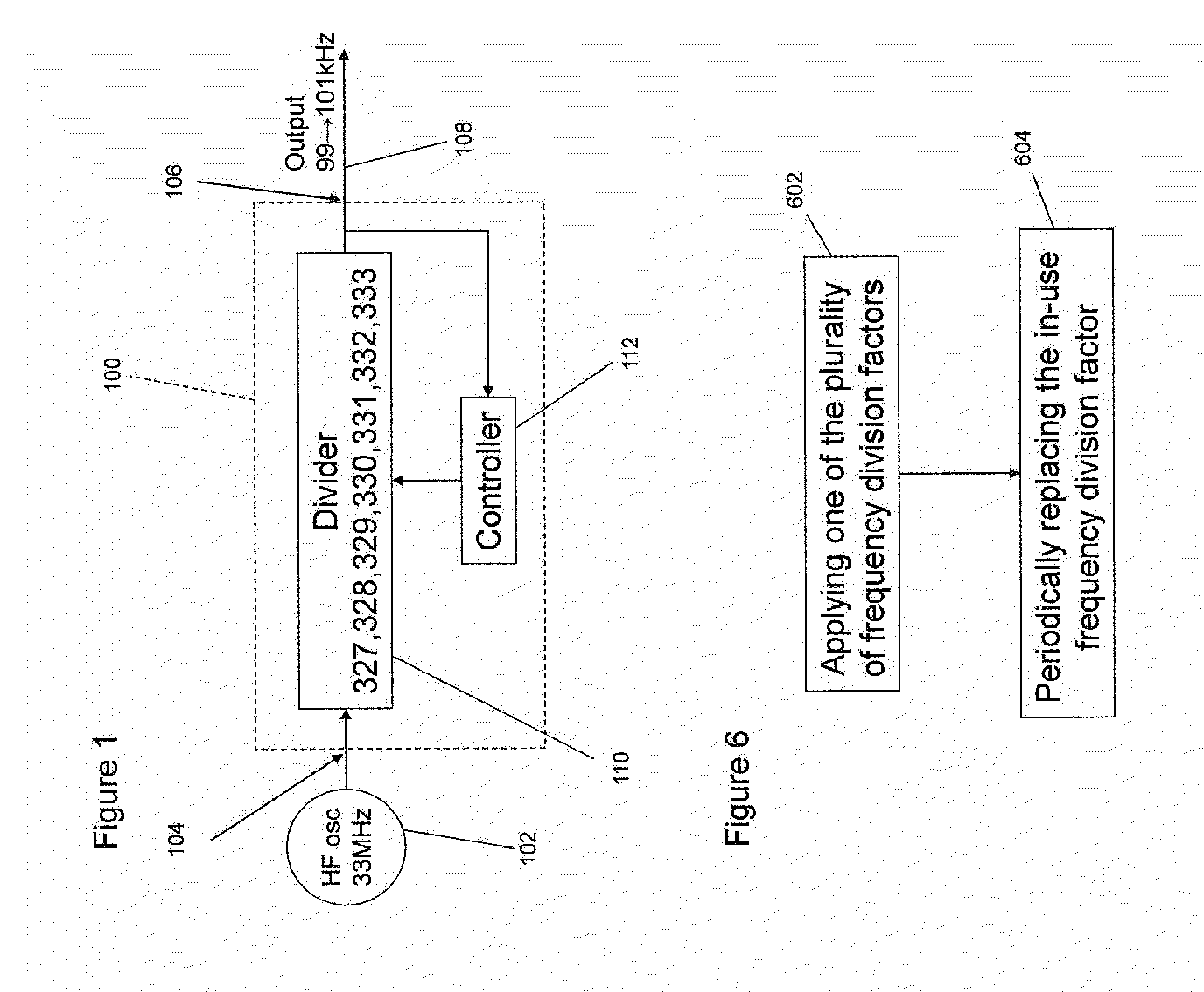
[0070]One or more embodiments described herein relate to a clock signal generator for providing a clock signal from a received oscillator signal. The clock signal generator can include a frequency divider to apply one of a plurality of frequency division factors to the oscillator signal in order to generate the clock signal. The clock signal generator can also include a controller that periodically replaces an in-use frequency division factor with another of the plurality of frequency division factors in order to adjust the frequency of the clock signal. This may be known as applying frequency jitter.

[0071]In this way, the frequency of the clock signal can be adjusted over time so that any electromagnetic interference (EMI) can be spread out over a frequency range. As an example, the frequency of the clock signal may vary by 1% around a central frequency value.

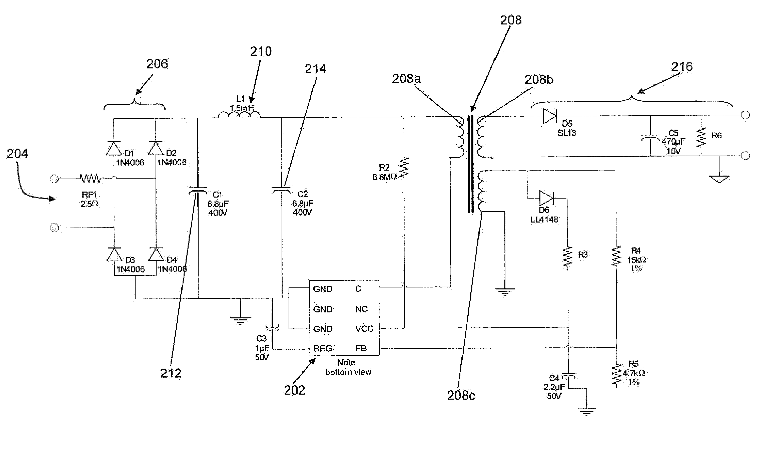
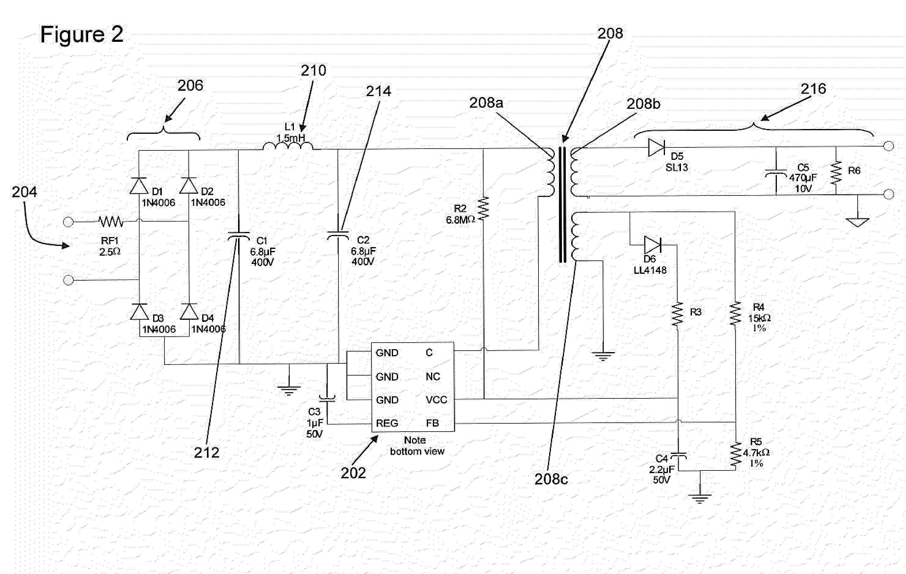
[0072]The clock signal can be used by a pulse width modulation signal generator for use with a switched mode power supply (S...


PUM


Abstract

A clock signal generator comprising an input pin for receiving an oscillating signal and an output pin for providing a clock signal. The clock signal generator also comprises a frequency divider connected between the input pin and the output pin. The frequency divider having a plurality of frequency division factors associated therewith, wherein, in use, the frequency divider is configured to apply one of the plurality of frequency division factors as an in-use frequency division factor to the oscillating signal in order to generate the clock signal. The clock signal generator further comprising a controller configured to periodically replace the in-use frequency division factor with another of the plurality of frequency division factors.

Description

[0001]This application claims the priority under 35 U.S.C. §119 of European patent application no. 09290916.7, filed on Dec. 4, 2009, the contents of which are incorporated by reference herein.[0002]The present disclosure relates to the field of clock signal generators, and particularly, although not exclusively, clock signal generators that generate clock signals for switched mode power supplies.BACKGROUND OF THE INVENTION[0003]Electromagnetic interference (EMI) emissions from power supplies are an important problem and are often the cause of redesigns or additional costs in circuit design. EMI emissions are usually reduced by using control schemes such as zero voltage switching, valley switching, and frequency jittering.[0004]Other methods to create frequency jitter include oscillators with capacitor switching as disclosed in U.S. Pat. No. 7,026,851 (Yang et al), dual oscillators as disclosed in U.S. Pat. No. 6,107,815 (Balakirshnan et al) and U.S. Pat. No. 6,229,366 (Balakirshnan...

Claims


Application Information

Patent Timeline
Patent Type & Authority Applications(United States)
IPC IPC(8): H02J7/00H03L7/00H02M3/22G06F1/04
CPCH03L7/197
Inventor SINGH, FATEHUGUEN, EMERIC
Owner NXP BV
Why Eureka
Try Eureka