Method and apparatus for tuning frequency of LC-oscillators based on phase-tuning technique

Active Publication Date: 2011-12-08
THE HONG KONG UNIV OF SCI & TECH
View PDF4 Cites 17 Cited by
  • Summary
  • Abstract
  • Description
  • Claims
  • Application Information

AI Technical Summary

Benefits of technology

[0008]By properly deciding the phase shifting provided by the PT cell, the LC ring oscillator is configured to operate within a frequency range around the peak frequency of the main LC-tank in each stage. The frequency of the LC ring oscillator can be lower, higher or substantially equivalent to the peak frequency. The phase tuning method for the LC ring oscillator circumvents the disadvantages of conventional capacitive tuning, including the tank's quality factor degradation, AM-to-PM noise transformation, and limited tuning range with reduced supply voltage in deep sub-micron CMOS circuits. Moreover the multiple stages of the ring oscillator provide multiple noise filtering with an optimal Q factors in the LC-tank. As a result, the PT LC ring oscillator can generate high-frequency, wide-tuning-range and low-phase-noise output signals with multiple phases.
[0009]In a further embodiment, the PT LC-oscillator, which is implemented in a 0.13-μm CMOS process, generates 8-phase output signals with phase noises of −127.8 dBc / Hz at 10 MHz offset, tuning ranges of 6.8%, and figure of merits (FoMs) of −186.4 dB at 50 GHz, respectively. In another embodiment, the PT LC-oscillator, which is implemented in the 0.13-μm CMOS process, generates 4-phase output signals, with phase noises of −118.5 dBc / Hz at 10 MHz offset, tuning ranges of 9%, and figure of merits (FoMs) of −180.5 dB at 60 GHz, respectively. Compared with conventional integrated MMW frequency VCOs, the PT LC ring oscillators described herein provide much better in phase noise performance and more superior FoMs.

Problems solved by technology

The phase tuning method for the LC ring oscillator circumvents the disadvantages of conventional capacitive tuning, including the tank's quality factor degradation, AM-to-PM noise transformation, and limited tuning range with reduced supply voltage in deep sub-micron CMOS circuits.

Method used


Image

  • Method and apparatus for tuning frequency of LC-oscillators based on phase-tuning technique
  • Method and apparatus for tuning frequency of LC-oscillators based on phase-tuning technique
  • Method and apparatus for tuning frequency of LC-oscillators based on phase-tuning technique

Examples


Embodiment Construction

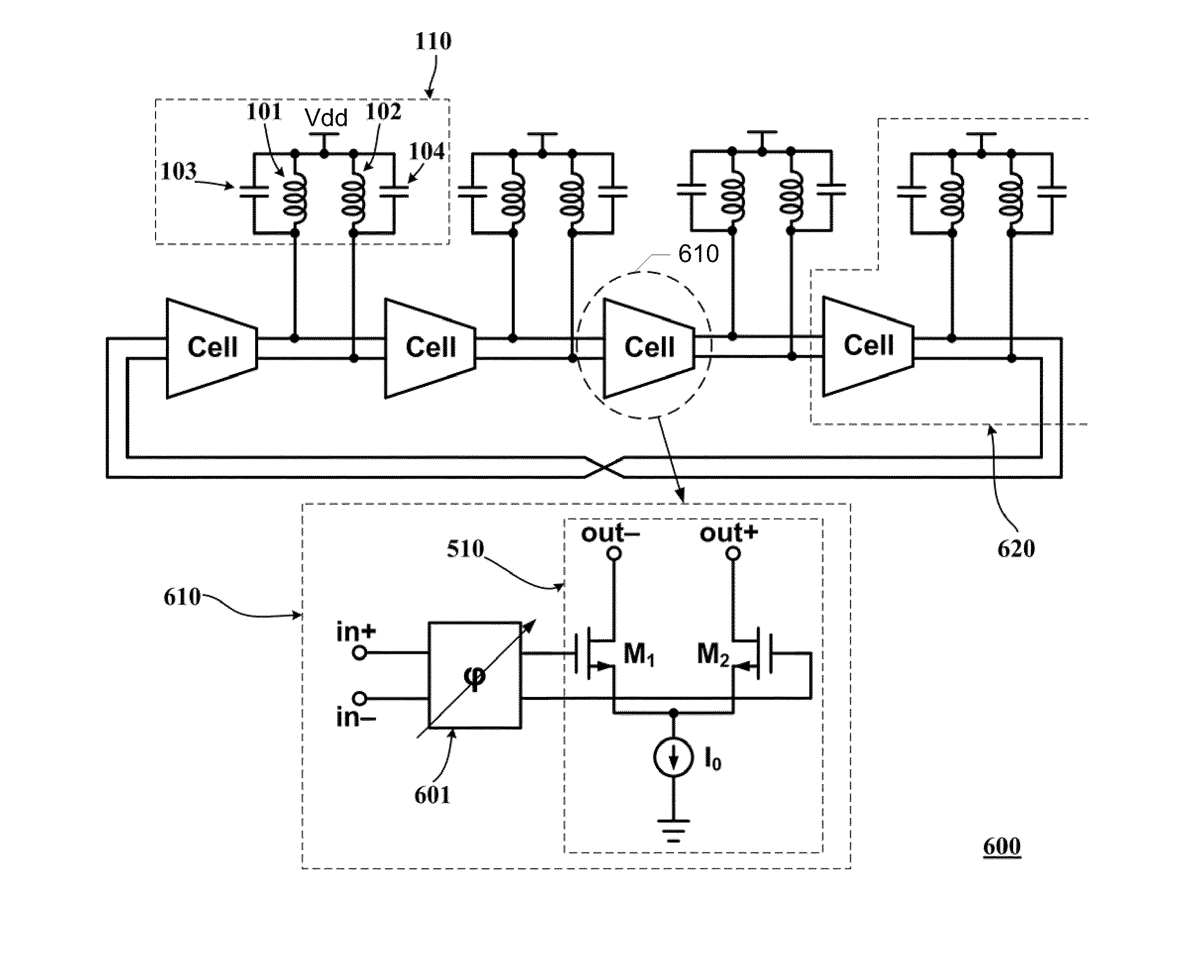
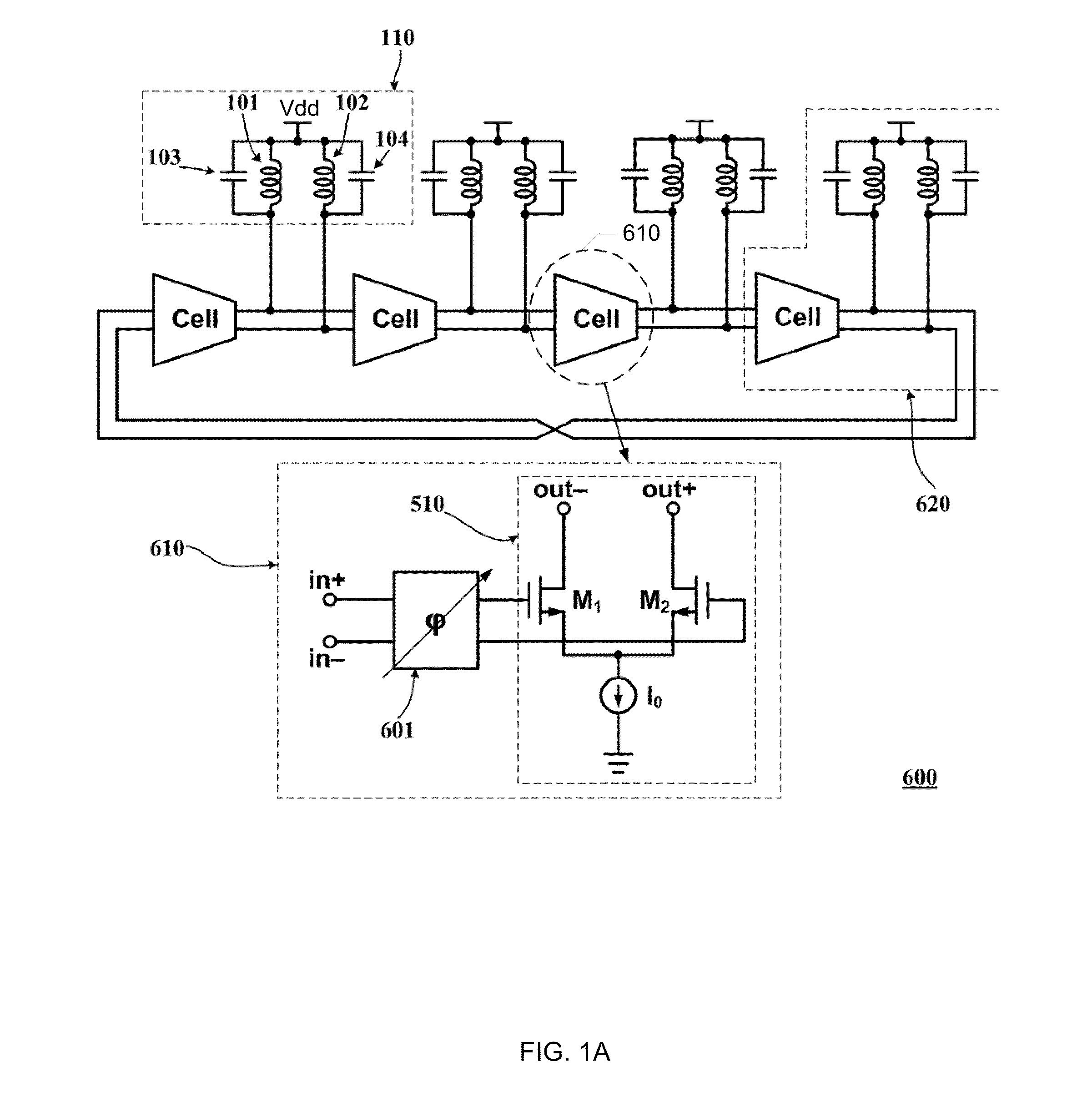
[0026]In general, the invention described herein provides a method for tuning the frequency of a multiphase ring oscillator, which includes a plurality of stages connected in series in a ring structure. According to various embodiments of the invention, a phase shift is introduced into an input signal of each stage and the phase of the output signal and hence the frequency of the ring oscillator is adjusted by varying the phase shift of the input signal.

[0027]According to some alternative embodiments as depicted in FIG. 9, a method 10 is provided to tune the frequency of the multiphase ring oscillator. According to this embodiment, when each stage of the ring oscillator receives an input signal (11), at least one phase shift is imparted to at least one portion of the input signal (12). A plurality of output signals are then generated from the phase shifted portions of the input signal (13). The plurality of the output signals are then combined to form a stage output (14), which is u...


PUM


Abstract

A tunable multiphase ring oscillator includes a plurality of stages connected in series in a ring structure, where each stage generating a stage output from a stage input. Each stage of the tunable multiphase ring oscillator includes a plurality of trans-conductance cells, each generating an output from at least one portion of the stage input. Each stage further includes at least one phase shifting module for imparting at least one phase shift to the at least one portion of the stage input, an oscillator unit for generating the stage output from a combination of the plurality of outputs, and means for varying at least one of the plurality outputs so as to adjust a phase of the stage output.

Description

FIELD OF THE INVENTION[0001]The present invention relates in general to the field of LC-oscillator and in particular to a multiphase LC-oscillator with a phase turning technique.BACKGROUND OF THE INVENTION[0002]LC-oscillators for generating high purity clock or local oscillation (LO) signals are the key building blocks in wire-line and wireless communication systems. And multiple phase clock and LO signals are required in the modern communication systems. In-phase and quadrature-phase (I&Q) signals are required in the zero-IF receivers for modulation or demodulation, and the prerequisites in image-rejection receivers such as Weaver or Hartley architecture. Multiphase LO or clock signals are also required for the phase-array applications and the half-rate clock-and-data recovery (CDR).[0003]In order to receive or transmit the signals from or to channels at different frequencies, as well as to handle process, voltage and temperature variations, the LC-oscillators are required to be fr...

Claims


Application Information

Patent Timeline
IPC IPC(8): H03K3/03
CPCH03B5/24H03B27/00H03K3/0322H03L7/0995H03B5/1225H03L7/0998H03B5/1221H03B5/124H03B5/1237H03B5/1256H03B5/1228
Inventor LUONG, HOWARD CAMRONG, SUJIANG
Owner THE HONG KONG UNIV OF SCI & TECH
Why Eureka
Try Eureka