Method and device for detecting azimuth

a technology of azimuth detection and method, applied in the direction of measurement devices, multi-channel direction-finding systems using radio waves, instruments, etc., can solve the problems of aliasing (ambiguity), difficult manufacturing, and the ability to identify azimuth only uniquely, so as to improve the resolution of azimuth detection, widen the range of azimuth detection, and simple configuration

Active Publication Date: 2011-12-08
DENSO CORP
View PDF13 Cites 55 Cited by
  • Summary
  • Abstract
  • Description
  • Claims
  • Application Information

AI Technical Summary

Benefits of technology

[0017]In the azimuth detecting device of the present disclosure configured as described above, processing equivalent to transmission beam switching is actualized without use of a phase controller by the spatial frequency analysis along the element array of the transmission-side antenna elements. Therefore, widening of an azimuth detection range can be actualized by a simple configuration.
[0018]In addition, in the azimuth detecting device of the present disclosure, as a result of two-dimensional frequency analysis being performed, azimuth is detected from a result of a combination of two characteristics determined based on the placement of the transmission-side antenna elements and the placement of the reception-side antenna elements. Therefore, for example, in the beam former, an effect of narrowing beam width is achieved, and resolution of azimuth detection can be improved.

Problems solved by technology

However, when the azimuth is detected using phase difference, so-called aliasing (ambiguity) occurs based on the inability to differentiate between phase differences Δφ and Δφ+360°.
Therefore, a problem occurs in that the azimuth can only be uniquely identified within a range in which the phase difference changes 360° (such as −180°<Δφ≦180°).
However, when a plurality of transmitting antennas each having a different beam directivity are used, the directions of the transmitting antennas are required to be precisely decided, and a problem occurs in that manufacturing becomes difficult.
However, a problem occurs in that actualization of these phase controllers is difficult in terms of performance and cost.

Method used


Image

  • Method and device for detecting azimuth
  • Method and device for detecting azimuth
  • Method and device for detecting azimuth

Examples


second embodiment

[0084]Referring to FIG. 8, the azimuth detecting device according to a second embodiment of the present invention will now be described.

[0085]A radar device 10 according to the second embodiment differs only in part from the radar device 1 according to the first embodiment. The difference will mainly be described.

[0086](Configuration)

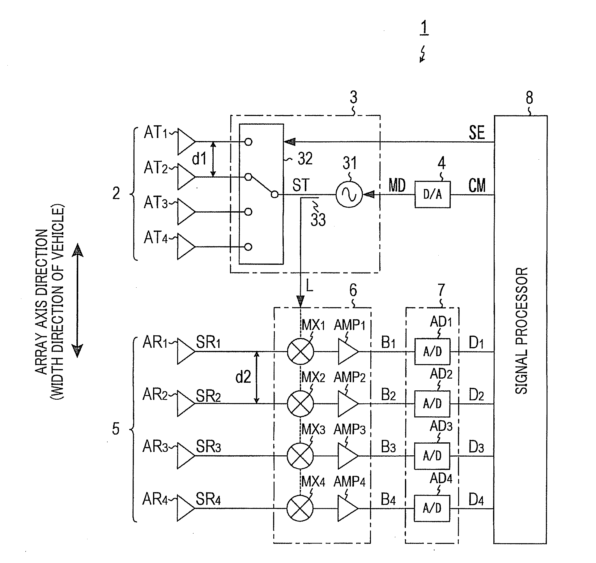
[0087]As shown in FIG. 8, the radar device 10 includes a transmission / receiving array antenna 12 composed of an M-number (M=4 according to the second embodiment) of antenna elements A1 to AM arrayed in a single row, instead of the transmission array antenna 2 and the receiving array antenna 5.

[0088]In addition, the radar device 10 includes, instead of the selector 33, directional couplers DJ1 to DJN respectively provided in the antenna elements A1 to AN, and a selector 13 that supplies the transmission signal ST to any of the directional couplers DJ1 to DJN (and thus, the antenna elements A1 to AN) in adherence to the selection signal SE from the signal...


PUM


Abstract

A device for detecting an azimuth has a transmission array antenna having plural transmission antenna elements arrayed along an array axis and a receiving array antenna having plural receiving antenna elements arrayed along the array axis. A reception signal is acquired for each of channels by transmitting and receiving a search wave through each of the channels. The channels are arbitrary combinations of each of the transmission antenna elements and each of the receiving antenna elements. A first spatial frequency analysis is performed along the array axis of either ones of the transmission antenna elements and the receiving antenna elements using the reception signal. A second spatial frequency analysis is then performed along the array axis of the other ones of the antenna elements using results of the first spatial frequency analysis. An azimuth of a target is determined based on analysis results from the second spatial frequency analysis.

Description

CROSS-REFERENCE TO RELATED APPLICATION[0001]This application is based on and claims the benefit of priority from earlier Japanese Patent Application No. 2010-129200 filed Jun. 4, 2010, the description of which is incorporated herein by reference.BACKGROUND OF THE INVENTION[0002]1. Field of the Invention[0003]The present invention relates to a method and device for detecting azimuth (i.e., azimuth direction, orientation, or direction) of a target based on a reflected wave from the target received by a plurality of receiving antennas.[0004]2. Description of the Related Art[0005]Conventionally, a radar device, called a phase-monopulse radar device, is known in which a plurality of receiving antennas receive a reflected wave emitted from a transmitting antenna and returned by being reflected by a target, and an azimuth of the target is detected from a shift in phase (in other words, phase difference) of a receiving signal at each receiving antenna.[0006]However, when the azimuth is dete...

Claims


Application Information

Patent Timeline
Patent Type & Authority Applications(United States)
IPC IPC(8): G01S13/02
CPCG01S3/74G01S13/48G01S13/32
Inventor MIZUTANI, AKIYOSHINAKABAYASHI, KENTONATSUME, KAZUMA
Owner DENSO CORP
Why Eureka
Try Eureka