Method for hydrophilizing surfaces of ink pathway

Inactive Publication Date: 2011-12-08
MEMJET TECH LTD
5 Cites 1 Cited by

AI-Extracted Technical Summary

Problems solved by technology

The formation of such bubbles causes blockages in the ink flow, reduces the wettability of the surfaces, and degrades print quality.
The hydrophilic characteristics conveyed to surfaces by plasma activation, however, degrade or relax with time.
Keeping a printhead assembly primed with ink, or an ink like fluid, from the time of production until the time of use, however, introduces significant complexities, including the storage and transport of such primed printhead assemblies.
PEI is therefore understood to be less effective when used on surfaces activated with a plasma other than a carbon dioxide plasma.
Vacuum plasma processing methods, however, are expensive and time consuming.
A vacuum plasma processing method requires costly and specialised equipment to create a vacuum and to generate a plasma within the vacuum.
Further, significant time is required for loading and unloading a work piece into/from a vacuum chamber, creating and releasing the vacuum, and a...

Benefits of technology

[0076]removing the protective metal film so as to reveal the hydrophobic coating, and thereby ...

Abstract

A method of hydrophilizing surfaces of an ink pathway configured for supplying ink to nozzles in an inkjet printhead. The method includes the steps of: treating the surfaces of the ink pathway with a solution comprising an alkoxylated polyethyleneimine; and drying the surfaces.

Application Domain

Inking apparatusWriting implements +3

Technology Topic

HydrophilizationEngineering +2

Image

  • Method for hydrophilizing surfaces of ink pathway
  • Method for hydrophilizing surfaces of ink pathway
  • Method for hydrophilizing surfaces of ink pathway

Examples

  • Experimental program(3)

Example

First Embodiment for Treating Ink Pathways
[0136]FIG. 17 is a flow chart illustrating the steps of a first embodiment of the hydrophilizing method of the present invention.
[0137]A newly fabricated printhead assembly is first subjected to a plasma activation process (S2-1). In the first embodiment, an O2 plasma is used. The O2 plasma activation process is performed with the printhead assembly at atmospheric pressure.
[0138]An atmospheric plasma generating tool (such as those available from Surfx Technologies LLC) is preferably utilized as the plasma source, allowing the printhead assembly to be maintained in an environment at or close to atmospheric pressure. Alternatively, an arrangement utilizing corona discharge directed at the printhead assembly may be used.
[0139]Following the plasma activation process (S2-1), the activated printhead assembly is packaged into a print cartridge assembly, whereupon it is primed with ink and the print cartridge assembly subjected to a print quality and electrical testing process (S2-2).
[0140]The activated surfaces of the printhead assembly, having raised surface energies, facilitate the rapid ingress of ink into the fluidic channels of the printhead assembly during the print quality and electrical testing process (S2-2). The ink used in the print quality and testing process is comprised of water, water soluble glycols, dyes and surfactants, and hence does not compromise the wetting character of the plasma activated surfaces. The print quality and electrical testing process (S2-2) utilising such ink therefore does not result in any significant deterioration in the hydrophilicity of the printhead assembly generated through exposure to the plasma.
[0141]Purging of unused ink, post testing, and rinsing of the printhead assembly with either an ink like vehicle comprising ink like components without a soluble dye, or water, with or without surfactants (S2-3), returns the print quality tested assembly to a condition that retains sufficient surface activation and hydrophilicity.
[0142]In an exemplary print quality and electrical testing process, an ink priming test and electrical test of the print cartridge assembly is performed. Then, the print cartridge assembly is washed with deionized water at 40 KPa through the back channels of the printhead assembly, and the water vacuum extracted over 3 cycles at a reduced pressure of −40 KPa at ambient temperature.
[0143]Following the purging process (S2-3), the printhead assembly is disassembled from the print cartridge assembly.
[0144]As previously mentioned, although the surfaces of the printhead assembly are hydrophilic after the oxygen plasma activation process (S2-1), the activated surfaces relax over time and invariably return to a less-hydrophilic state. To minimize relaxation of the activated surfaces and loss of hydrophilicity, the first embodiment performs a treatment process (S2-4) on the surfaces of the printhead assembly, whereby the internal, active surfaces of the printhead assembly are exposed to an EPI treatment solution. The treatment process (S2-4) is performed after the purging process (S2-3).
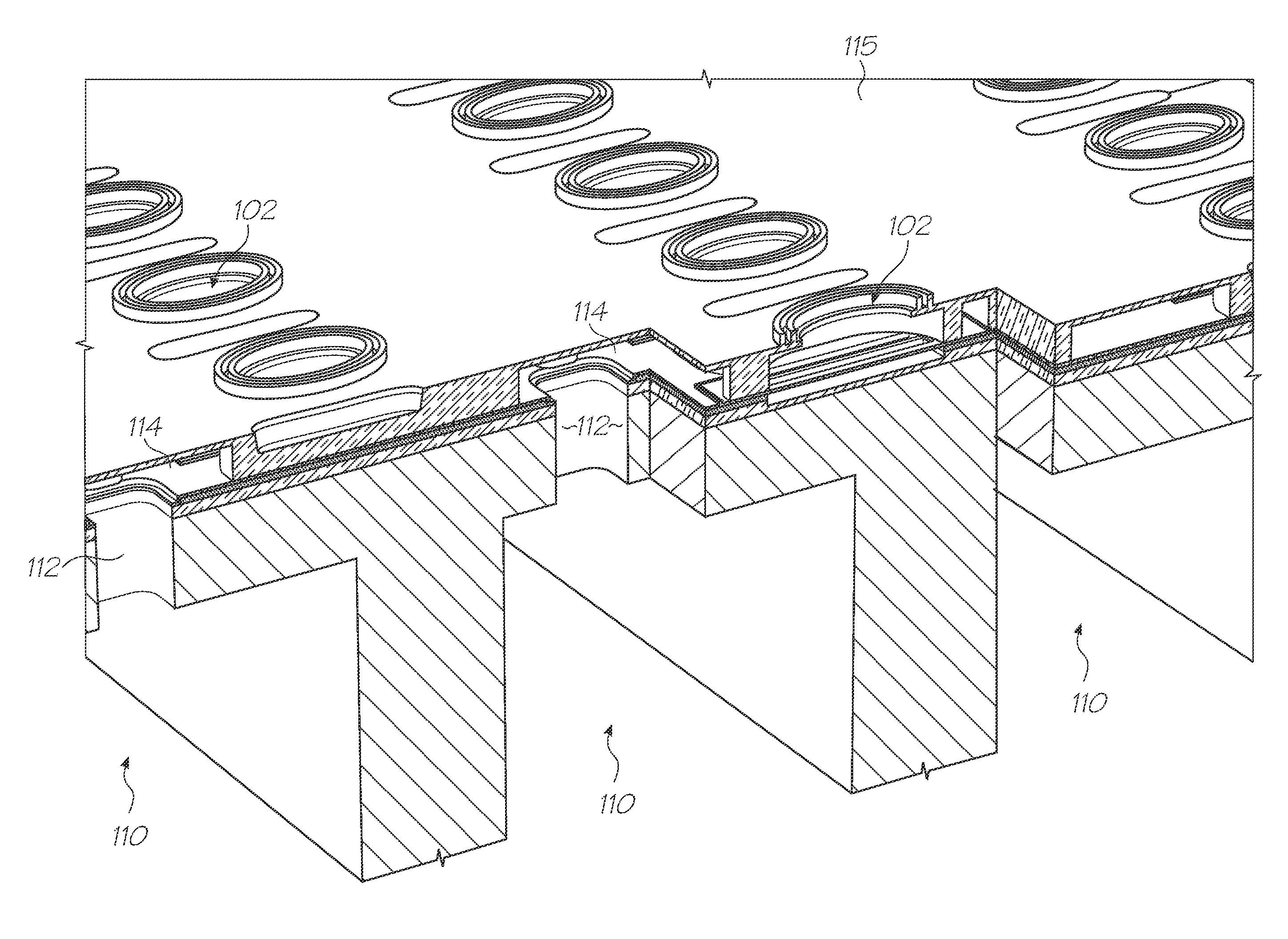
[0145]The treatment process (S2-4) injects an EPI treatment solution though the ink pathways of the printhead assembly. The treatment solution may be injected through the ink inlets 127 and/or ink outlets 128 of the printhead assembly 130 to the nozzles 102. Alternatively, the treatment solution may be injected from the nozzles 102 so as to also flush contaminants that may have accumulated from the print quality and electrical testing process (S2-2).
[0146]To ensure complete exposure of the printhead assembly's internal structure to the treatment solution, the ink pathways of the printhead assembly are blocked and/or subjected to a regime of pressure pulses. The pressure pulses cause a surge flow which dislodges any bubbles that may have been pinned during injection of the treatment solution. Pressure pulsing further compresses any such bubbles, thereby further aiding their release. The ink pathways can be treated either collectively or individually for each color channel. The treatment of individual color channels allows for greater control over the process as variations in reagent flow can be monitored.
[0147]As EPI is supplied commercially as a concentrated solution in water, typically between 35 and 40%, a treatment solution containing EPI is preferably formed by further diluting the EPI concentrate with a compatible solvent. In the present embodiment, water is used as it is safe to handle (non-toxic, non-flammable), cheap and easy to dispose off Furthermore, water does not deactivate high energy surfaces, has itself a high surface tension, and while volatile, does not dry too quickly. Overly quick drying of the EPI solution may cause irretrievable blockages in the micro fluid structures of the printhead assembly
[0148]Propylene glycol, or other glycols and glycol ethers such as polyethylene glycol-300, with comparable volatility, may further be added to the EPI solution to slow down the drying rate of the EPI solution, allowing the EPI solution to stay fluid for the duration of the process.
[0149]An exemplary formulation (by percentage mass) of an EPI treatment solution is as follows: [0150] EPI (0.01% to 10%); typically 0.1% [0151] Propylene glycol (0.1% to 30%); typically 10%/Alternatively, Polyethylene glycol-300 (0.1%- to 30%); typically 10% [0152] Surfactant—e.g. Surfonyl® (0.01% to 5%); typically 0.1% [0153] Water (remaining mass)
[0154]Following the treatment process (S2-4), the treated printhead assembly is dried (S2-5).
[0155]In an exemplary drying process, purified compressed air is applied to each channel of the printhead assembly at a pressure of 600 KPa. A pressure line is connected to the printhead assembly via an on-off tap or stopcock, and the purified compressed air pulsed through the ink channels by rotating the tap. Since the passage of gas through the fluidic path of each channel is determined by the complexity of its structure and the degree of restriction offered by its smallest feature, pulsing the compressed air ensures that all of the treatment solution is purged from the fluidic path, including any accumulated excess fluid that may have pooled within the printhead assembly's fluidic structure. The frequency and number of pulsing operations is determined based on the effective dryness of the purged printhead. One to six cycles of 10 seconds duration per cycle was found to be effective, but the drying process is not so limited. All channels are subsequently blown through with warm air at 800 KPa for 10 minutes. The warm air is preferably generated by a vortex device, whereby the generated air is substantially free of contaminants. In the exemplary drying process, the printhead assembly is finally placed in an oven at 70° C. for 2 or more hours, with the nozzles of the printhead assembly pointing upwards.
[0156]The process of drying the treated printhead substantially removes any water and propylene glycol introduced from the treatment solution. A non-volatile, highly wetting, thin film of EPI is left behind on the surfaces of ink pathways in the printhead assembly 130.
[0157]As mentioned above, the treatment solution is a water based solution of an EPI concentrate. Solvation of EPI in water is achieved through hydrogen bonding interactions of water molecules with appropriate receptor sites, viz. the ethoxy and/or amino functionalities of which EPI is comprised. To achieve adhesion of EPI to the hydrogen bonding sites on the activated surface of the printhead assembly, however, the water molecules associated with solvation must be persuaded to leave the treatment solution and allow the hydroxyl groups at the activated surface to take their place. This is most effectively achieved through the thermal displacement of the solvent, i.e. baking.
[0158]Baking serves to drive off water molecules, while the excess thermal energy allows the EPI to more rapidly maximise its surface interaction and achieve a stable surface coating. Baking also helps to volatilize any residual propylene glycol left after the drying process. Accordingly, the dried printhead assembly is preferably reassembled into the printhead cartridge and baked/cured in an oven (S2-6). Preferably, the printhead cartridge is cured for 1 to 18 hours at approximately 70° C.
[0159]In the first embodiment, the treatment process (S2-4) and drying process (S2-5) are performed after the print quality and electrical testing process (S2-2). In this manner, the thin film of EPI left behind after the drying process (S2-5) is untouched and unaffected by any further processes.

Example

Second Embodiment for Treating Ink Pathways
[0160]FIG. 18 is a flow chart illustrating the steps of a second embodiment of the hydrophilizing method of the present invention.
[0161]In the second embodiment, a newly fabricated printhead assembly is first subjected to a plasma activation process (S3-1). Similar to the first embodiment, an O2 plasma is used. The plasma activation process (S3-1) is performed with the printhead assembly at atmospheric pressure.
[0162]An atmospheric plasma generating tool is preferably utilized as the plasma source. Alternatively, an arrangement utilizing corona discharge directed at the printhead assembly may be used.
[0163]Following activation of the printhead assembly, (S3-1) a decontamination process (S3-2) is performed. The decontamination process (S3-2) flushes a cleaning fluid through the printhead assembly 130.
[0164]Acceptable cleaning fluids include Surfynol® in deionized water, aqueous glycols and alcohols, other surfactants in deionized water, or a combination of such fluids. Common to these fluids are the characteristic of being water based, having good wetting characteristics, having low surface tension, solubilising of film forming contaminants, volatile (to facilitate rapid drying), and leaving only residues compatible with subsequent wet processing. The cleaning fluids used should further be benign to the printhead assembly material (including glue joints and encapsulants), and preferably be non-toxic, cheap, readily available, and recyclable after filtration.
[0165]From the foregoing description of the printhead assembly 130, it will appreciated that the tortuous ink pathways gradually decrease in size from the back of the printhead assembly towards the front of the printhead assembly. The cleaning fluid is therefore reverse flushed from the nozzles 102 on a front face of the printhead assembly, out through the ink inlets 127 and/or ink outlets 128 on a back face. Reverse flushing ensures that the particles of contamination are propagated into channels of ever increasing size. In this manner, the particles of contamination are not trapped in the ink pathways, and do not block or become lodged in the narrower portions of the ink pathway.
[0166]In an exemplary decontamination process (S3-2), a reverse flush is performed at 200 ml/min for 200 seconds at 45° C. The printhead assembly 130 is then assembled to form a print cartridge assembly, and the print cartridge assembly washed using a slow pulse of a solution of glycerol and ethylene glycol in water with a soupcon of Surfynol® for 3 cycles, at 3-5 KPa, followed by one 6 second pulse at 80 KPa. The print cartridge assembly is subsequently disassembled back into a printhead assembly.
[0167]Following the decontamination process (S3-2), a treatment process (S3-3) using a treatment solution of EPI is performed on the printhead assembly.
[0168]The treatment process (S3-3) injects the treatment solution though the inkways of the printhead assembly 130. The treatment process (S3-3) is performed analogously with the treatment process (S2-4) described in connection first embodiment.
[0169]As with the first embodiment, the treatment solution of EPI is preferably formed by diluting an EPI concentrate with a compatible solvent. Propylene glycol may further be added to the EPI solution to slow down the drying rate of the EPI solution, allowing the EPI solution to stay fluid for the duration of the process.
[0170]A drying process (S3-4) is performed after the treatment process (S3-3). The drying process (S3-4) is performed analogously with the drying process (S2-5) described in connection with the first embodiment
[0171]The process of drying the treated printhead assembly removes any water and propylene glycol introduced by the treatment solution. A non-volatile, highly wetting, thin film of EPI is left behind on the surfaces of the printhead assembly.
[0172]After drying, the printhead assembly is reassembled into the printhead cartridge, and baked/cured in an oven (S3-5). The baking step (S3-5) is performed analogously to the baking step (S2-6) described in connection with the first embodiment. Preferably, the printhead cartridge is baked for 1 to 18 hours at approximately 70° C.
[0173]Finally, a print quality and electrical testing process (S3-6) similar to that described in the first embodiment at (S2-2) is performed on the print cartridge assembly, and the print cartridge assembly allowed to sit for a day to dry.
[0174]The second embodiment, as compared to the first embodiment, includes an additional decontamination process (S3-2) performed after the plasma activation process (S3-1), but before the treatment process (S3-3). The decontamination process removes particulate contamination and film forming debris from the internal surfaces of the printhead assembly. In this manner, a more efficient and thorough treatment of the internal surfaces is realized.
[0175]Further, in the second embodiment, the print quality and electrical testing process (S3-6) is performed after the treatment process (S3-3) and the drying process (S3-4). While the passing of ink through the printhead assembly during the print quality and electrical testing process (S3-6) will dissolve some of the thin film EPI coating the internal surfaces, the rate of dissolution of the thin film is slow, and the time taken to print, test, wash and clean is short in comparison to the time needed to completely dissolve the thin film.
[0176]An advantage of performing the treatment process (S3-3) before the print quality and electrical testing process (S3-6), however, is that the treatment process (S3-3) is performed on freshly decontaminated surfaces that have not been exposed to any other substances, such as the inks and flushing fluids used during the print quality and electrical testing process (S3-6). In this manner, a more thorough and efficient treatment of the surfaces is realized.

Example

[0177]FIG. 19 is a flow chart illustrating a third embodiment of the hydrophilizing method of the present invention.
[0178]In the third embodiment, a printhead assembly is subjected first to a decontamination process (S4-1). The decontamination process (S4-1) reverse flushes a cleaning fluid through the printhead assembly. A reverse flush is performed for reasons as described above in the second embodiment.
[0179]It is particularly important in the third embodiment to have no residues left on the internal surfaces of the printhead assembly after the decontamination process (S4-1), since a later step of plasma activation in the third embodiment will by default activate any material the plasma comes into contact with, no matter what this material is, including surfactant residues left behind by the cleaning fluids. The internal surfaces of the assembly should also be completely dried before plasma activation, since residual water, or any fluid, would mask the surface from the plasma species passing over it. While an activated surfactant residue would very likely be highly wetting, a subsequent process of treatment to be performed in the third embodiment might well be compromised.
[0180]To leave a truly decontaminated, residue free surface, the cleaning fluid should contain no non-volatile components, and to facilitate drying is preferably readily removed upon exposure to heat. In the third embodiment, therefore, a solvent (such as an alcohol) is used in place of a surfactant, as the cleaning fluid.
[0181]Aqueous ethanol is a particularly effective solvent satisfying the above requirements. Propan-1-ol, would also be an effective solvent. Aqueous ethanol has a lower surface tension than water alone and is therefore more wetting. Furthermore, ethanol is a good solvent, evaporates easily, is cheap, relatively safe when diluted, non-toxic and readily available in pure form. Therefore, the third embodiment of the present invention preferably reverse flushes aqueous ethanol as a cleaning fluid in the decontamination process (S4-1).
[0182]The cleaning fluid of aqueous ethanol is subsequently thoroughly dried off, thereby completing the decontamination process (S4-1). In an exemplary decontamination process, the printhead assembly is vacuum dried in oven at approximately 70° C. for 2 hours.
[0183]Following the decontamination process (S4-1), the printhead assembly is subjected to a plasma activation process (S4-2). Similar to the first embodiment, an O2 plasma is used. The plasma activation process is performed with the printhead assembly at atmospheric pressure.
[0184]An atmospheric plasma generating tool is preferably utilized as the plasma source, allowing the printhead assembly to be maintained in an environment at or close to atmospheric pressure. Alternatively, an arrangement utilizing corona discharge directed at, or drawn through the printhead assembly may be used.
[0185]Following the plasma activation process (S4-2), the printhead assembly 130 is subjected to a treatment process (S4-3) using a treatment solution of EPI. The treatment process (S4-3) is performed analogously with the treatment process (S2-4) described in connection first embodiment
[0186]The treated printhead assembly is then dried (S4-4) analogously with the drying step (S2-5) described in connection with the first embodiment.
[0187]Following the drying process (S4-4), the printhead assembly is baked/cured in an oven at approximately 70° C. for 1 to 18 hours (S4-5), analogously with the baking step (S2-6) described in connection with the first embodiment.
[0188]Following the baking process (S4-5), the printhead assembly is assembled as a print cartridge assembly, and tested for print quality and electrical connections (S4-6). The print quality and electrical testing process is similar to that described in the first embodiment at (S2-2).
[0189]In the third embodiment, the decontamination process (S4-1) is performed as one of the first steps of the hydrophilizing method. By performing the decontamination process (S4-1) before the plasma activation process (S4-2), the internal surfaces of the printhead assembly are better exposed to the plasma, and accordingly more complete and optimal surface activation is realized. In particular, particulates or films that might otherwise mask critical areas of the internal structure are removed before the internal surfaces are activated.
[0190]In contrast to the first and second embodiments, in which a plasma activation process is performed before a decontamination process, the presence of non-activated surface patches that are less receptive to treatment is significantly reduced.
[0191]Further, in the third embodiment, the treatment process (S4-3) is performed effectively immediately after the plasma activation process (S4-2). In this manner, the activated surfaces of the printhead assembly are given less time to relax as compared to the first and second embodiments, and are maintained near their most energetic states. Moreover, as the printhead assembly 130 is made up of a composite of materials, each having different relaxation times, the sooner the treatment process is performed after the plasma activation process, the more uniform the surface energy of the different materials making up the printhead assembly will remain.
[0192]Still further, compared to the second embodiment, by performing the treatment process (S4-3) immediately after the plasma activation process (S4-2) instead of intervening a decontamination process therebetween, the treatment process (S4-3) is performed on a freshly activated surface that has not been exposed to other substances, such as those used in the decontamination process (S4-1).
[0193]Similar to the second embodiment, the print quality and electrical testing process (S4-6) is performed after the treatment process (S4-3). While the passing of ink through the printhead assembly during the print quality and electrical testing process (S4-6) will dissolve some of the thin film EPI coating the internal surfaces, the rate of dissolution of the thin film is slow, and the time taken to print, test, wash and clean is short in comparison to the time needed to completely dissolve the thin film.
[0194]As with the second embodiment, the advantage of performing the treatment process (S4-3) before the print quality and electrical testing process (S4-6) is that the treatment process (S4-3) is performed on freshly decontaminated surfaces that have not been exposed to any other substances, such as the inks and flushing fluids used during the print quality and electrical testing process (S4-6). Accordingly, an even more efficient and thorough treatment of the surfaces is realized.
Post-Processing Packaging and Shipping
[0195]The surfaces of a printhead assembly plasma activated and treated according to the disclosed embodiments above are coated with a non-volatile, highly wetting, thin film of EPI that inhibits relaxation of the activated surfaces.
[0196]The EPI thin film provides a relaxation-inhibiting effect similar or superior to the wet shipping method described above, whereby the printhead assembly 130 is primed with ink (or an ink like fluid) after fabrication, and remains primed with ink (or an ink like fluid) until use (hereinafter referred to as “wet shipping”). However, the present invention achieves hydrophilizing of ink pathway surfaces, with excellent longevity, without the complexities and inefficiencies associated with wet shipping.
[0197]Wet shipping printhead assemblies require the printhead assemblies to be packed in waterproof, perfectly sealed bags. Wet shipping printhead assemblies are intolerant to any deterioration of the sealed environment, and are further susceptible to ink spillage. In contrast, the non-volatile, highly-wetting EPI thin film coating the surfaces of a printhead assembly processed by the disclosed embodiments are macroscopically dry. Accordingly, special packing and sealing requirements are not necessary.
[0198]In a further embodiment of the present invention, therefore, printhead assemblies are packaged using more cost efficient packaging than is required for the wet shipping of a printhead assembly. Examples of such packaging include lower grade vacuum packaging, and shrink wrapping.
[0199]In a still further embodiment, the printhead assemblies are pre-installed in respective printers, and stored and transported with the printer. The printhead assemblies are stored and transported in a manner insensitive to orientation, allowing for more spatial and time efficient handling of the printhead assemblies throughout the logistics chain, and accordingly, significant cost savings. Storage, transport, and sale of printhead assemblies in this manner are possible since ink spillage from the printhead assemblies during these stages of the logistical chain is entirely prevented.
[0200]Moreover, compliance with import/export regulations, shipping classifications, customs classifications, and other legal and procedural complexities involved with the transport of liquids are obviated. Provision of a true “Plug and Play” printing system is also realized.
Experimental Section
[0201]A series of experiments will now be described, which demonstrate the superior hydrophilizing of properties of alkoylated polyethyleneimines, especially when compared with their polyethyleneimine counterparts and other polyelectrolytes. Furthermore, the compatibility of alkoylated polyethyleneimines with processes for fabricating printheads with hydrophobic coatings will also be demonstrated.
Luviquat® Treatment (Comparative Example)
[0202]Luviquats® are a range of cationic polymers, supplied by BASF. For example, Luviquat® PQ11 (polyquaternium-11) is supplied as an aqueous solution containing a quaternized copolymer of vinylpyrrolidone and dimethlyaminomethylmethacrylate. A Luviquat® treatment was initially trialled in order to investigate whether any polyelectrolyte treatment could retard relaxation of a plasma-activated surface, in accordance with a simple polyelectrolyte ionic interaction model.
[0203]A blank silicon tile (20 mm×10 mm) was provided having one silicon oxide surface and an opposite silicon nitride surface. Using the Wilhelmy plate technique the advancing contact angle of the native tile was found to be about 50-60°. In the Wilhelmy plate technique, the tile is immersed slowly into a liquid and the force measured by a sensitive balance. The measured force is the sum of the wetting force, the weight of the plate and the buoyancy. The advancing contact angle is then determined by solving the equation:
Wetting force=sP cos θ
where s is the liquid surface tension, P is the perimeter of the plate and θ is the advancing contact angle.
[0204]The retreating contact angle may be similarly determined by measuring the force when the plate is raised from the liquid.
[0205]In order to investigate the hydrophilizing effect of Luviquat® treatment, the silicon tile was treated as follows: [0206] washed with acetone and deionized water [0207] plasma activation (“ashing”) with an oxygen plasma for 60 seconds [0208] Luviquat® treatment by immersing for 5 minutes in solution.
[0209]Immediately after the plasma/Luviquat® treatment, the tile was found to have an advancing contact angle of about 20°. When left to age under atmospheric conditions for 39 days, the hydrophilicity decreased significantly. After 39 days ageing, the advancing contact angle of the plasma/Luviquat® treated tile was measured to be about 45°.
[0210]By way of comparison, a tile having a simple oxygen plasma treatment (with no subsequent Luviquat® treatment) had an initial contact angle of 0°, which increased to about 35° after ageing in atmosphere for 39 days.
[0211]It was therefore concluded that the Luviquat® treatment had no effect in improving the hydrophilic robustness of a plasma-treated surface. In fact, the Luviquat® treatment appeared to have a deleterious effect on the hydrophilicity of the treated tile. Accordingly, it was concluded that the polyelectrolyte ionic bonding model proposed by Sheu et al (Sheu et al, Polymer Surface and Interfaces: Characterization, Modification and Application, 1997, pp 83-90) was probably flawed. Moreover, it was concluded that Luviquat® treatment was not a viable method for enabling dry shipment of printheads having hydrophilic ink pathways.
Comparison of PEI and EPI Treatments on Silicon and Polymer Substrates
[0212]Polyethyleneimines (PEI) are a class of polymer formed by the polymerization of aziridines. They contain a mixture of primary, second and tertiary amine functionalities, have excellent water solubility and are readily available in a range of molecular weights. As discussed above, Sheu et al have demonstrated the hydrohilizing properties of PEI, following activation of a surface with carbon dioxide. Alkoxylation of polyethyleneimines (typically using an alkylene oxide) yields alkoxylated polyethyleneimines (or, more formally, “hydroxyalkylated polyethyleneimines”). For example, ethoxylated polyethyleneimine (EPI) is a well-known, commercially available polymer which is used as a dispersant in laundry detergents. In ethoxylated polyethyleneimines, a number (e.g. about 80%) of the primary and second amine functionalities are ethoxylated (“hydroxyethylated”). A range of ethoxylated polyethyleneimines are available from Sigma Aldrich as well as from BASF under the trade name Lupasol®.
[0213]A selection of ink pathway surfaces found in the printhead assembly 130 described above were investigated using PEI and EPI treatments. Three substrates were investigated:
[0214](1) an LCP token (“LCP”), modelling the LCP ink supply manifold comprised of the main LCP molding 122 and the LCP channel molding 124;
[0215](2) a strip of cured die attach film (“DAF”), modelling the die attach film 120 having cured external epoxy surfaces on either side of a polyimide layer
[0216](3) a silicon tile (“Si”), modelling the surfaces of the ink supply channels 110 in the printhead.
[0217]All three substrates were attached to a glass microscope slide and treated as follows: [0218] washed with methanol and dried with warm air from a hair dryer [0219] plasma-activated using a Surfx tool operating at 120 W with a helium flow rate of 0.20 L/min and an oxygen flow rate of 11.0 L/min. The surfaces were treated with two passes of the plasma at a traverse rate of 5 mm/s [0220] treated immediately with 1 mL of a methanolic solution containing either PEI or EPI and a fluorosurfactant (Zonyl® FS-300). The PEI had a molecular weight (Mn) of 423 Da; the EPI was 80% ethoxylated and had a molecular weight (Mn) of 50 kDa. [0221] blow dried with compressed air at 50 kPa [0222] stored at 60° C. in a standard oven
[0223]After treatment and storage, the substrates were tested for hydrophilicity using a standard drop spread technique. The drop spread technique is suitable for estimating the relative hydrophilicity of surfaces having low contact angles. In each case, a 35 microliter droplet of cyan ink was dispensed onto the surface and the size of the droplet spread measured. To some extent, the polymer surfaces gave irregular drop spreads, but the silicon surface gave consistently symmetrical drop spreads. The drop spread results are shown in Table 1. Irregular drop spreads are marked with an asterisk (*).
TABLE 1 Comparison of PEI and EPI treatments after O2 plasma activation Days 2.5% PEI + 0.5% 5% PEI + 1% 2.5% EPI + 0.5% at surfactant surfactant surfactant 60° C. LCP DAF Si LCP DAF Si LCP DAF Si 1 0.59 0.59 0.73 0.59 0.59 0.71 0.77 0.73 0.75 2 0.58 0.51 0.62 0.56 0.55 0.70 0.70 0.82 0.81 5 0.78* 0.57 0.70 0.62 0.76* 0.70 0.85 0.64 0.77 7 0.73 0.67* 0.73 0.76 0.80* 0.72 0.78 0.95* 0.78 22 0.66 0.47 0.53 0.63 0.54* 0.57 0.70 0.58 0.74
[0224]From the results shown in Table 1, it can be seen that the EPI treated surfaces showed a consistently higher degree of drop spread for all surface types. Silicon tiles treated with EPI returned consistently to very high hydrophilicity (as evidenced by drop spread), even after prolonged storage. At all times, EPI treatment of the silicon surface and the polymer surfaces generally outperformed the PEI treatment.
[0225]Since the silicon surface of ink supply channel 110 in the printhead assembly 130 is the most important surface in terms of priming and printhead performance, and since experimental observations were consistently more reliable for the silicon surface, subsequent experiments focused on the silicon surface.
Comparison of Different Molecular Weight PEIs and EPIs on Silicon Substrate
[0226]Following on from the results presented in Table 1, further experiments were conducted to investigate the effect (if any) of the molecular weight of the PEI and EPI polymers.
[0227]Five PEI samples, ranging in molecular weight from 1.2 kDa to ˜1 MDa, and two EPI samples (80% ethoxylated) of molecular weight 50 kDa and 70 kDa (all purchased from Sigma Aldrich) were assessed. The polymers were formulated in a wetting vehicle consisting of: propylene glycol (10%), Surfynol® (0.1%) and Proxel® (0.1%).
[0228]As described previously, silicon tiles were attached to clean microscope slides with double-sided tape and then washed with acetone (−5 mL) and deionized water (−5 mL) before being dried with warm air from a hairdryer.
[0229]Each tile was plasma-activated using a Surfx tool operating at 120 W with a helium flow rate of 0.2 L/min and an oxygen flow rate of 11.0 L/min. The surfaces were treated with two passes of the plasma at a traverse rate of 5 mm/s
[0230]Immediately after plasma-activation, the tiles were wetted with 0.5 mL of 1% EPI or PEI formulated in the wetting vehicle, and blown dry with compressed air at 40 kPa. By way of control, some tiles were plasma treated only and were not exposed to any wetting solutions. The prepared tiles were stored at 70° C. in a conventional oven and representative samples were removed periodically for standard drop spread analysis. The drop spread results are shown in Table 2.
TABLE 2 Comparison of wetting characteristics for different PEIs and EPIs Treatment solution Drop spread (mm) on Si after storage at 70° C. (1%) Mn 18 hours 2 days 6 days 14 days PEI 1.2K 1.2 kDa 6.4 5.9 6.5 7.3 PEI 1.8K 1.8 kDa 5.9 6.1 6.8 7.6 PEI 10K 10 kDa 6.1 6.5 7.0 7.3 PEI 60K 60 kDa 5.9 5.9 7.1 7.8 PEI 1M 1 MDa 5.8 5.7 6.8 7.6 EPI 50K 50 kDa 7.6 7.0 7.1 8.2 EPI 70K 70 kDa 7.4 6.8 7.3 8.2 None n/a 7.2 6.4 4.8 3.5 (plasma only)
[0231]All five of the PEI-treated samples showed an apparent increase in hydrophilicity upon storage. This general trend was mirrored by the two EPI-treated samples and suggests there may be a maturation, or increase, in hydrophilicity upon elevated temperature storage. There appeared to be no compelling evidence that an optimal wetting performance is associated with any particular molecular weight polymer.
[0232]Of greater significance, however, was the consistently higher wetting performance of tiles treated with the ethoxylated polyethyleimines. The EPI-treated tiles exhibited far better wetting than any of the PEI-treated tiles.
[0233]By way of control, tiles that were plasma treated alone showed a rapid decline in surface wettability, consistent with the known relaxation of plasma-activated silicon surfaces and more fully demonstrating the permanent and excellent hydrophilizing character of EPI treatments. The contact angles of EPI-treated silicon tiles were estimated to be 4° or less, even after prolonged storage and exposure to atmospheric conditions.
EPI-Treatment Process Variations
[0234]The EPI-treatment protocol, as described above, was investigated with various processes so as to mimic possible printhead treatments prior to dry shipment.
[0235]Silicon tiles were attached to microscope slides and prepared as described earlier. Combinations of four process steps were evaluated.
(1) The first process (“PIWD”) combined 4 steps:
[0236]P: Atmospheric oxygen plasma activation.
[0237]I: Ink-dipped (cyan ink) for 30 seconds.
[0238]W: DI water washed (until judged clean) and blown dry.
[0239]D: Dipped in a 0.1% solution of EPI (50 KDa in wetting vehicle) and blown dry.
(2) The second process (“IWD”) combined 3 steps:
[0240]I: Ink-dipped (cyan ink) for 30 seconds.
[0241]W: DI water washed (until judged clean) and blown dry.
[0242]D: Dipped in a 0.1% solution of EPI (50 KDa in wetting vehicle) and blown dry.
(3) The third process (“PD”) combined 2 steps:
[0243]P: Atmospheric oxygen plasma.
[0244]D: Dipped in a 0.1% solution of EPI (50 KDa in wetting vehicle) and blown dry.
(4) The fourth process (“P”) involved plasma activation only and no wet treatment:
[0245]P: Atmospheric oxygen plasma.
[0246]The conditions under which plasma activation, EPI treatment and drop spread analysis were conducted were exactly as described above. The results are shown in Table 3.
TABLE 3 Effect of Different Processes on EPI-treatment Drop spread (mm) on Si after storage at 70° C. 0 10 20 35 Process days 1 day 2 days 5 days 7 days days days days PIWD 8.6 9.3 9.1 9.9 9.1 8.7 9.2 8.8 IWD 7.8 9.0 8.9 9.7 9.0 8.5 9.3 8.2 PD 8.6 9.0 9.5 9.7 8.9 8.5 9.0 9.6 P 7.8 7.2 6.4 4.8 4.2 3.5 3.2
[0247]The results in Table 3 demonstrate that the EPI-treatment may be incorporated into a variety of different printhead processing protocols and still retain its hydrophilic character.
[0248]The resistance of EPI to “wash-off” is clearly an important parameter and it appears that drying, preferably baking, is essential so as to ensure adhesion of the EPI to the surface via hydrogen bonding. Without at least a drying step, the EPI can be readily washed off rendering the surface less hydrophilic.
[0249]Remarkably, treatment of EPI on a non-activated surface (“IWD”) still provided a very hydrophilic surface with excellent robustness and longevity. Therefore, plasma-activation of the surface is not, in fact, essential, although optimal hydrophilization is still achieved when the EPI treatment is performed immediately after plasma-activation.
Treatment of Non-Activated Silicon Substrates
[0250]Having established that EPI, surprisingly, hydrophilizes non-activated silicon surfaces, the robustness of such treatments was investigated more thoroughly. Silicon tiles were prepared and treated with EPI solutions as described in Table 4.
TABLE 4 EPI Treatments on Non-Activated Silicon Substrates Drop spread Drop spread (mm) at 0.1% (mm) at 1.0% Treatment Process Description EPI EPI 1 Dipped into EPI solution 4.7 4.6 (in wetting vehicle) and immediately washed off with deionized water 2 Dipped into EPI solution 7.4 8.1 and blown dry before washing off with DI water 3 Dipped into EPI solution, 7.9 7.0 blown dry and not washed off 4 Dipped into EPI solution, 8.2 7.4 blown dry and baked for 1 min at 70° C. 5 Dipped into EPI solution, 8.1 9.3 blown dry, baked for 1 min at 70° C. and then washed with DI water 6 Dipper in DI water, blown 4.0 4.0 dry and baked for 1 min at 70° C.
[0251]This series of treatments confirmed that EPI treatment hydrophilizes non-activated silicon substrates. Furthermore, it was established that drying of the EPI film is essential (comparing Treatment 1 with Treatments 2-5), and that baking improves uniformity and performance. There appeared to be no real advantage in adopting higher concentrations of active.
Compatibility of EPI Treatments With Processes for Fabricating Hydrophobically-Coated Printheads
[0252]As already discussed herein, the Applicant has developed processes for fabricating printheads having a hydrophobic coating disposed on the nozzle plate 115. The hydrophobic coating may be a polymerized siloxane, such as polydimethylsiloxane or a polysilsesquioxance, although other hydrophobic polymer coatings are equally possible using the methods described in the Applicant's US Publication Nos. 2008/0225077 and 2009/0139961.
[0253]A series of experiments were performed to investigate the compatibility of the EPI treatments described above with printheads having a hydrophobic polymer coating.
[0254]Initially, a PDMS-coated wafer was exposed to an oxygen plasma at atmospheric pressure and then dipped in a 0.1% solution of EPI in the wetting vehicle described above. The wafer was blown dry and then baked in an oven at 70° C. In subsequent drop spread analyses, the PDMS layer consistently had drop spreads of about 9 mm, even after baking for 3 days, indicating the PDMS layer had become robustly hydrophilic. By contrast, a PDMS-coated wafer exposed to an oxygen plasma without subsequent EPI treatment recovered rapidly (relaxed) to its original hydrophobic state. Therefore, it was concluded that the EPI treatment protocol could not be used with exposed polymer printhead coatings (e.g. polymerized siloxane coatings), because the polymer coating did not relax after treatment with EPI.
[0255]Following these initial experiments with PDMS-coated wafers, the compatibility of methods for removing the aluminium film 90 with EPI-treated printhead materials were then investigated.
[0256]It was found that treatment with a 2.5% solution of tetramethylammonium hydroxide (TMAH) successfully stripped the aluminium film 90 from a PDMS-coated wafer without adversely affecting the hydrophilicity of other printhead materials, which had received the EPI treatment. In particular, it was found that a cured adhesive film 120 and an LCP coupon which had received the EPI-treatment could be subsequently treated with TMAH and still retain their wetting behaviour after rinsing and drying.
[0257]Therefore, it was concluded that a wet etch under basic conditions (i.e. pH>7) to remove the aluminium film 90 was fully compatible with the EPI-treatment. Thus, a suitable process for providing printhead assemblies having hydrophilic ink pathways and a hydrophobic ink ejection face comprises the steps of:
[0258](i) assembling the printhead assembly 130 using the aluminium-protected printhead ICs shown in FIGS. 15 and 16;
[0259](ii) exposing the printhead assembly 130 to an O2 plasma and treating ink pathways with an EPI solution; and
[0260](iii) removing the aluminium film 90 to reveal the hydrophobic polymer 80 disposed on the nozzle plate 115 of the printhead.
[0261]Of course, variants of this process in accordance with the first, second and third embodiments described above are within the ambit of the present invention.
[0262]Although the invention has been described herein with reference to a number of specific embodiments, it will be appreciated by those skilled in the art that the invention is not limited only to the disclosed embodiments, and that these embodiments described a best-mode/preferred embodiment, whereas the invention may be embodied in other forms encompassed within the scope of this invention.

PUM

PropertyMeasurementUnit
Temperature40.0 ~ 100.0°C
Fraction0.01 ~ 0.99fraction
Fraction0.047fraction

Description & Claims & Application Information

We can also present the details of the Description, Claims and Application information to help users get a comprehensive understanding of the technical details of the patent, such as background art, summary of invention, brief description of drawings, description of embodiments, and other original content. On the other hand, users can also determine the specific scope of protection of the technology through the list of claims; as well as understand the changes in the life cycle of the technology with the presentation of the patent timeline. Login to view more.
Why Eureka
Try Eureka