Electric power source device

a technology of electric power source and battery cell, which is applied in the direction of electrical equipment, cell temperature control, cell components, etc., can solve the problems of reducing battery performance, achieve the effect of suppressing incomings and outgoings, increasing the effect of heating battery cells, and reducing the effect of incomings and outgoings

Inactive Publication Date: 2011-12-08
DENSO CORP
View PDF2 Cites 58 Cited by
  • Summary
  • Abstract
  • Description
  • Claims
  • Application Information

AI Technical Summary

Benefits of technology

[0008]According to the above feature of the invention, the battery casing accommodating the multiple battery cells has the heat insulating structure at the portion surrounding the battery cells. It is, therefore, possible to suppress incomings and outgoings of heat between an inside and an outside of the battery casing. The power source device having a function of keeping the battery cells warm can be realized. In addition, since the heating unit is provided between the lower surfaces of the battery cells and the bottom portion of the battery casing, the air in the battery casing can be heated by the heating unit, whether or not the heating unit is directly or indirectly in contact with the battery cells. Therefore, the natural convection of the air, in which the heat is transferred from a lower portion toward an upper portion, is generated. As a result, temperature difference between the lower and upper portions of the battery casing and the battery cells can be balanced and thereby the b

Problems solved by technology

Therefore, it is a problem that ba

Method used


Image

  • Electric power source device
  • Electric power source device
  • Electric power source device

Examples


first embodiment

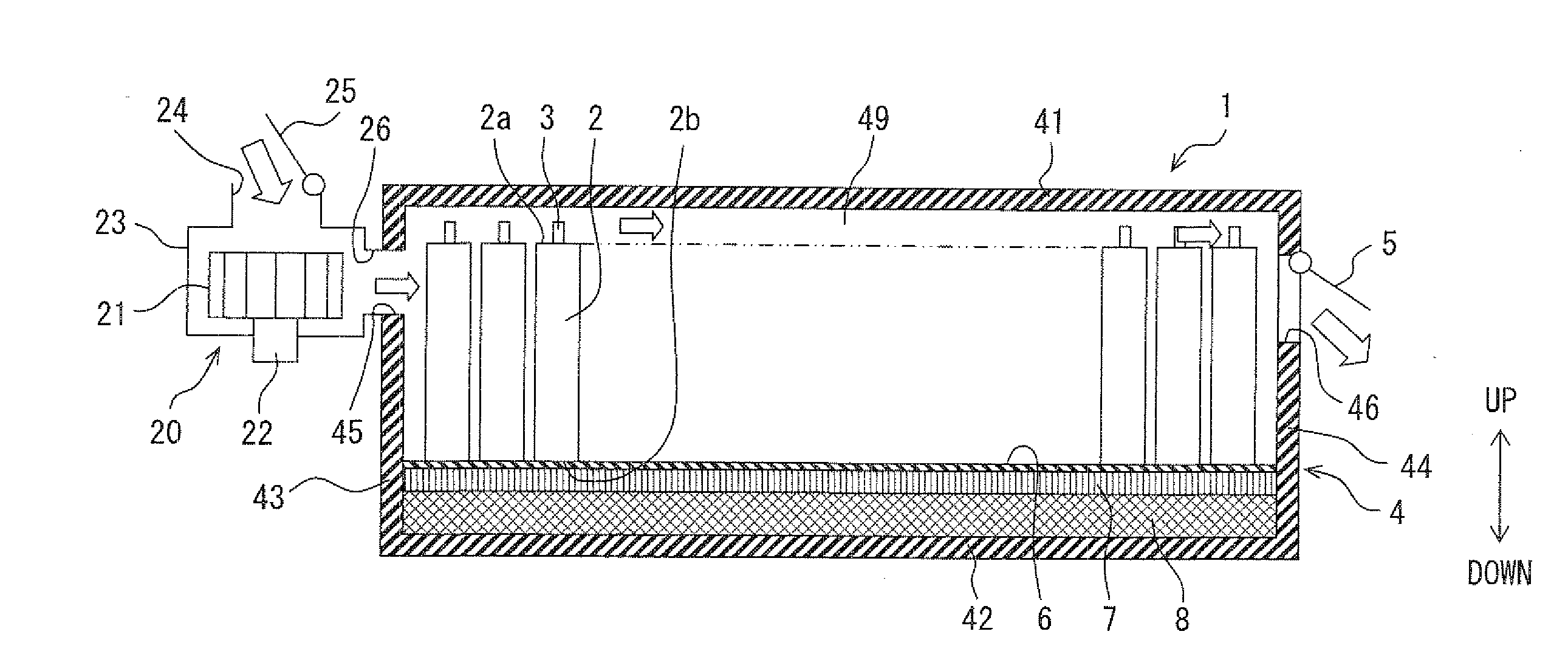
[0022]An electric power source device of the present invention is applied to a hybrid vehicle having a driving power source combining an internal combustion engine with an electric motor operated by electric power charged in a battery, or the present invention may be further applied to an electric vehicle having a driving power source of an electric motor. The electric power source device supplies electric power to such a vehicle driving motor. The electric power is charged in respective battery cells forming a battery pack. Each of the battery cells is composed of, for example, a nickel metal-hydride secondary battery, a lithium-ion secondary battery, an organic radial battery and so on. The battery cells are accommodated in a battery casing, which is located in a space beneath a vehicle seat, a space between a rear seat and a trunk room, a space between a driver seat and a passenger seat and so on.

[0023]A first embodiment of the present invention will be explained with reference t...

second embodiment

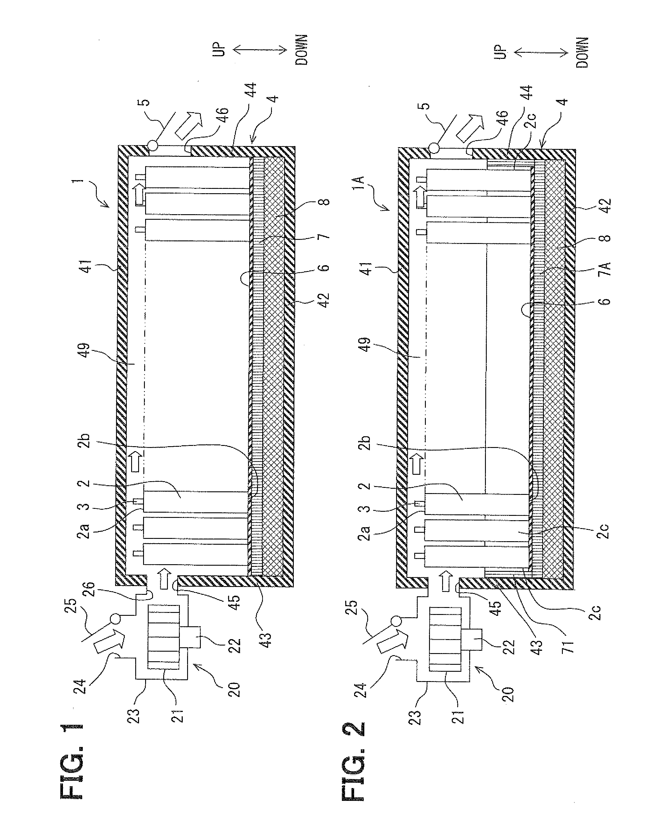
[0049]An electric power source device 1A according to a second embodiment will be explained with reference to FIG. 2. FIG. 2 is a schematic cross sectional view showing an inside structure of the battery casing 4 of the electric power source device 1A.

[0050]As shown in FIG. 2, the power source device 1A has a second heating unit 71 at side surfaces 2c of the battery cells 2 such that the second heating unit 71 surrounds the battery cells 2 in a circumferential direction. The power source device 1A has a first heating unit 7A, which is identical to the heating unit 7 of the first embodiment. The second heating unit 71 as well as the first heating unit 7A is made in the same manner to the heating unit 7 and has the same effect to the heating unit 7. The other structure of the second embodiment is the same to that of the first embodiment.

[0051]According to the power source device 1A, the first heating unit 7A is provided between the lower surfaces 2b of the battery cells 2 and the bott...

third embodiment

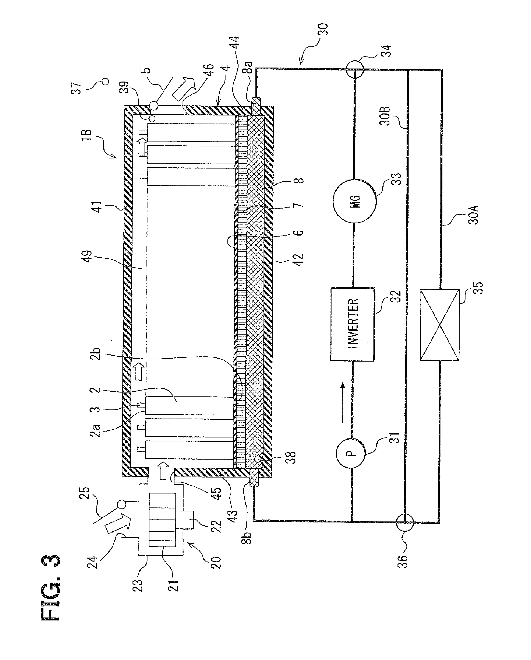
[0052]An electric power source device 1B according to a third embodiment will be explained with reference to FIG. 3. FIG. 3 is a schematic view showing a structure for a warm-keeping function of the electric power source device 1B.

[0053]As shown in FIG. 3, the power source device 1B has a first cooling water circuit 30, which is a closed circuit being composed of a pump 31, an inverter 32, a motor generator 33 and the heat storage layer 8. The power source device 1B further has a second cooling water circuit 30A, which connects an inlet-side passage of the first cooling water circuit 30 with an outlet-side passage of the first cooling water circuit 30. The inlet-side passage is connected to an inlet portion 8a of the heat storage layer 8, while the outlet-side passage is connected to an outlet portion 8b of the heat storage layer 8. A heat exchanger 35 is provided in the second cooling water circuit 30A. In addition, the power source device 1B has a bypass circuit 30B, which bypasse...


PUM


Abstract

An electric power source device has multiple layered battery cells which are electrically connected in series and/or in parallel. The battery cells are accommodated in a battery casing, which has a heat insulating structure at a portion surrounding the battery cells. The power source device further has a heating unit between lower surfaces of the battery cells and a bottom plate of the battery casing. A heat storage layer is further provided between the heating unit and the bottom plate for storing the heat generated at the heating unit.

Description

CROSS REFERENCE TO RELATED APPLICATION[0001]This application is based on Japanese Patent Applications No. 2010-129055 filed on Jun. 4, 2010 and No. 2011-089438 filed on Apr. 13, 2011, the disclosures of which are incorporated herein by reference.FIELD OF THE INVENTION[0002]The present invention relates to an electric power source device having an aggregate, in which multiple battery cells are layered, for supplying electric power to an electric motor and so onBACKGROUND OF THE INVENTION[0003]An electric power source device for an electric vehicle is known in the art, for example, as disclosed in Japanese Patent Publication No. 2008-140630, according to which multiple batteries are built in a battery casing. The conventional power source device has a hollow heat insulating layer at a lower side of the battery casing. Heat transfer fluid is filled in the hollow heat insulating layer, so that the heat transfer fluid can be moved in the inside thereof. According to such power source dev...

Claims


Application Information

Patent Timeline
IPC IPC(8): H01M2/36H01M10/50H01M2/10H01M10/60H01M10/613H01M10/615H01M10/625H01M10/647H01M10/653H01M10/6556H01M10/6563H01M10/6568H01M10/6571H01M10/658H01M10/659H01M10/667
CPCH01M10/5006H01M10/5059H01M10/5016H01M10/615H01M10/625H01M10/6557Y02E60/10
Inventor IRITANI, KUNIOINOUE, YOSHIMITSU
Owner DENSO CORP
Why Eureka
Try Eureka