High-resolution microscopy and photolithography devices using focusing micromirrors

a micromirror and high-resolution technology, applied in the field of high-resolution microscopy and microlithography, can solve the problems of preventing high-resolution polychromatic light, limiting its resolution, and intrinsically suffering from chromatic aberration

Active Publication Date: 2011-12-08
ECOLE POLYTECHNIQUE FEDERALE DE LAUSANNE (EPFL)
View PDF4 Cites 79 Cited by
  • Summary
  • Abstract
  • Description
  • Claims
  • Application Information

AI Technical Summary

Benefits of technology

[0017]In the microlithography configuration, a sample of photo-polymerizable material is positioned in the focal area of the micromirror array. Light whose temporal and spatial intensity profile can be controlled is made incident on the micromirror array for photo-polymerizing the material located at the foci of micromirror. Stage-scanning of the sample synchronized to the writing laser operation thus allows micromachining of two or three-dimensional structures.

Problems solved by technology

Still, the limitations of this system are the low NA of microlenses (NA<0.6) in comparison to microscope objectives, severely restricting its resolution, especially in the axial direction.
Furthermore, microlenses are intrinsically suffering from chromatic aberration, which prevents high resolution with polychromatic light.
But, the restricted numerical aperture (NA) and intrinsic chromatic aberration of microlenses severely limits its resolution and confines its range of application to monochromatic light.
While zone-plates can achieve NAs comparable to the NA of a microscope objective, they are limited to operating at a single designed wavelength, because of the diffractive focusing process involved.
Therefore, they cannot function properly with polychromatic light.

Method used


Image

  • High-resolution microscopy and photolithography devices using focusing micromirrors
  • High-resolution microscopy and photolithography devices using focusing micromirrors
  • High-resolution microscopy and photolithography devices using focusing micromirrors

Examples


first example

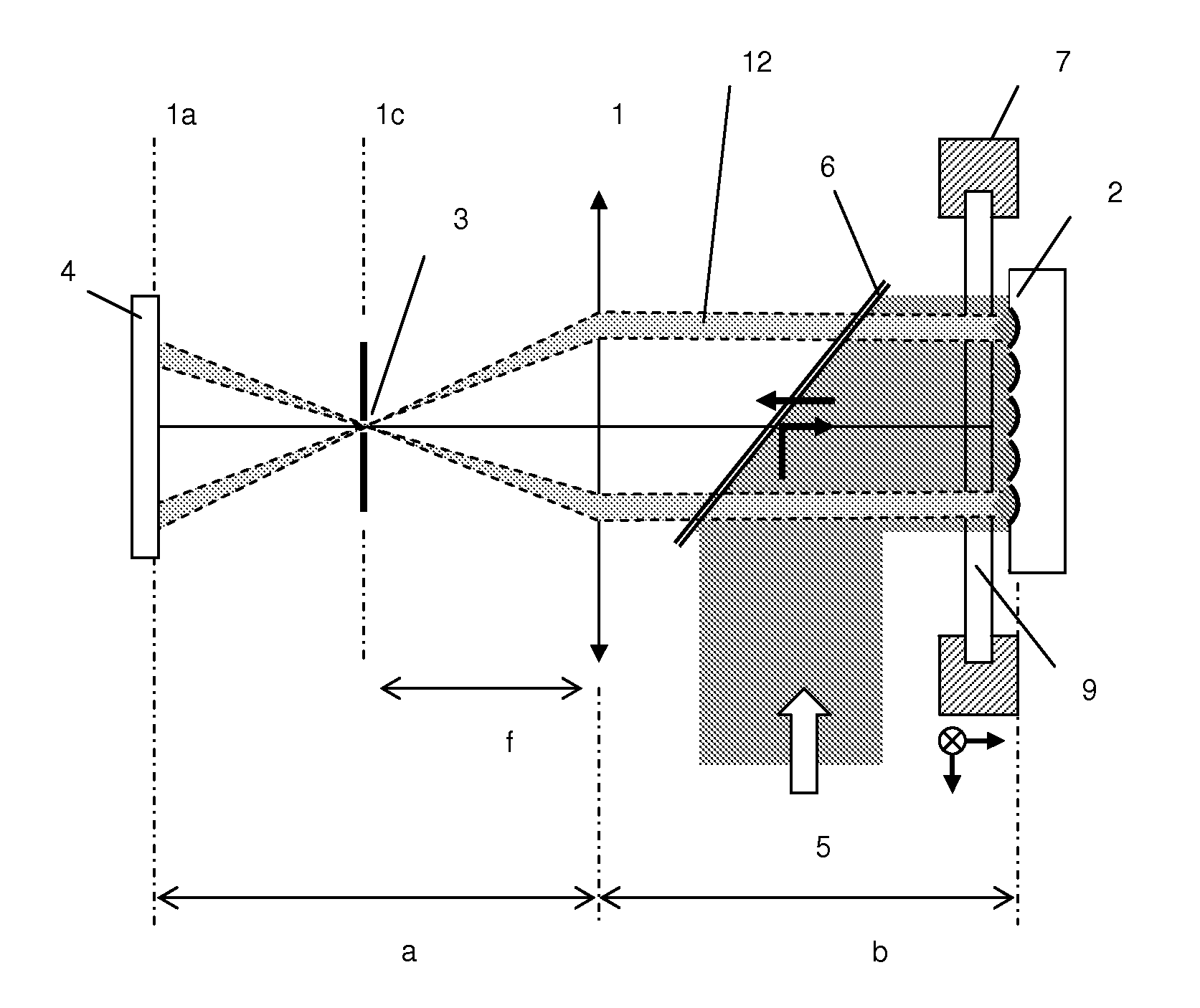
Micromirrors Array for Large Field Confocal Microscopy

[0044]Confocal scanning microscopy is a nowadays widely used technique, whether it is for biological or micromanufacturing applications. Since resolution is now brought down the micron, high NA is a requirement and mirrors have the potential to provide it while operating in array format. They can notably improve some of the actual systems limitations. One is the field of view limitation of most confocal microscopes that appears to use beam scanning within a high NA objective. The scan is indeed done within the field of view of the objective, rather small if providing high NA. A single focusing mirror would not overstep this limitation but the present invention proposes to use micromirrors arranged in a two dimensional array in order to perform simultaneous multi-confocal detection for large-field imaging.

[0045]Besides, the increasing development of microsystems, particularly for biological and chemical applications, encourages th...


PUM

PropertyMeasurementUnit
diameteraaaaaaaaaa
diameteraaaaaaaaaa
diameteraaaaaaaaaa

Abstract

The invention relates to large-field high-resolution microscopy and photolithography setups operating with polychromatic light. It includes the use of a plurality of focusing micromirrors.

Description

FIELD OF INVENTION[0001]The present invention generally relates to high-resolution microscopy and microlithography. Its primary aimed application in the high-resolution microscopy domain would be parallel scanning confocal microscopy, with special emphasis on polychromatic light applications. The primary aimed application in the high-resolution microlithography domain is parallel micro- and nano-structuring based on two-photon polymerization with ultra-short pulsed lasers.[0002]The following description will mainly focus on confocal microscopy, with a few variants of the system presented for demonstrating the versatility of the invention. However, it is understood that the invention can be appropriately adapted to many other high resolution microscopy and microlithography procedures.BACKGROUND OF THE INVENTION[0003]Basically, confocal microscopy consists in a limitation of the field of illumination and of the field of view by means of spatial filtering of the light [1]. The result i...

Claims


Application Information

Patent Timeline
Patent Type & Authority Applications(United States)
IPC IPC(8): G03F7/20G02B21/14G03B27/54G02B21/08
CPCG02B21/0032G02B21/0076G02B21/004G02B26/0833G03F7/70191
Inventor RACHET, BASTIENMERENDA, FABRICESALATHE, RENE
Owner ECOLE POLYTECHNIQUE FEDERALE DE LAUSANNE (EPFL)
Why Eureka
Try Eureka