


Quick Research
Generate reliable direction feasibility study reports for your R&D in just a few steps.

Technical Q&A
Discover and master advanced knowledge NOW. Basics, ideas, possibilities, all at once.

Find Solutions
As an expert in R&D theories, this can generate solutions to your technical problems instantly.

Evaluate Feasibility
Analyze your overall solution with one click, know your potential R&D risks in advance.

Monitor Landscape
Get weekly tech updates, stay abreast of the latest tech innovations and key insights.
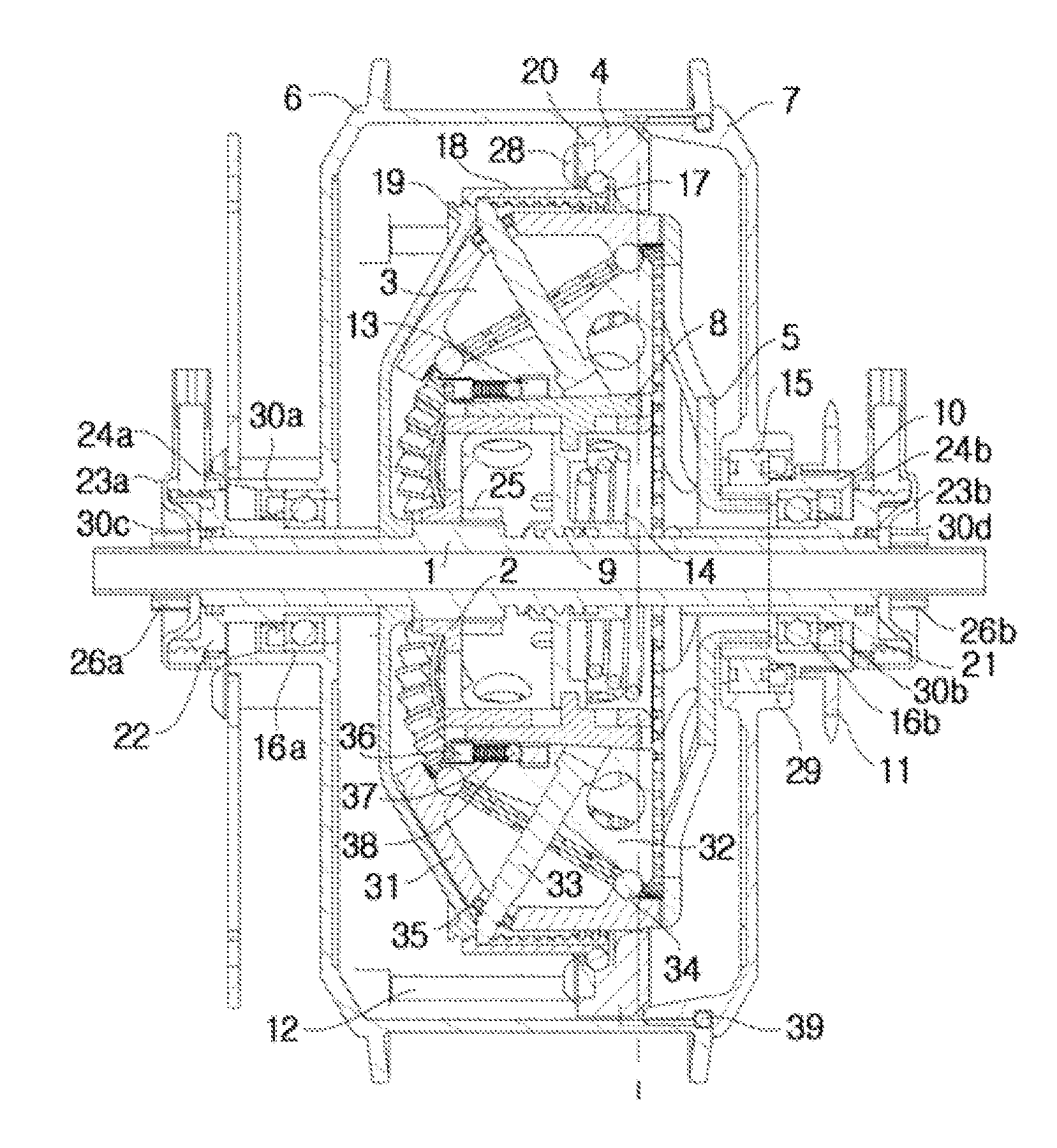
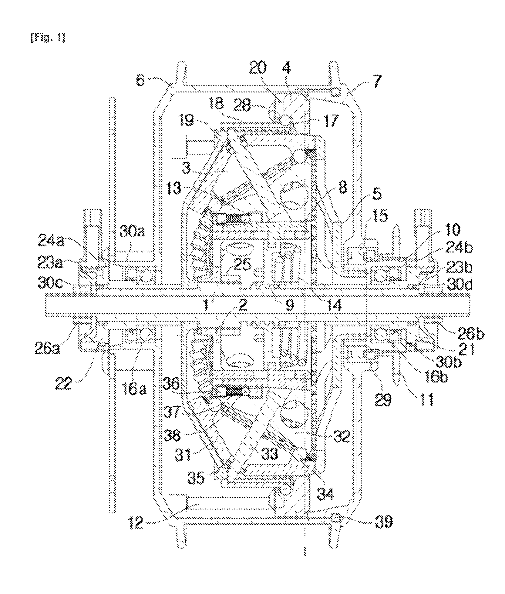
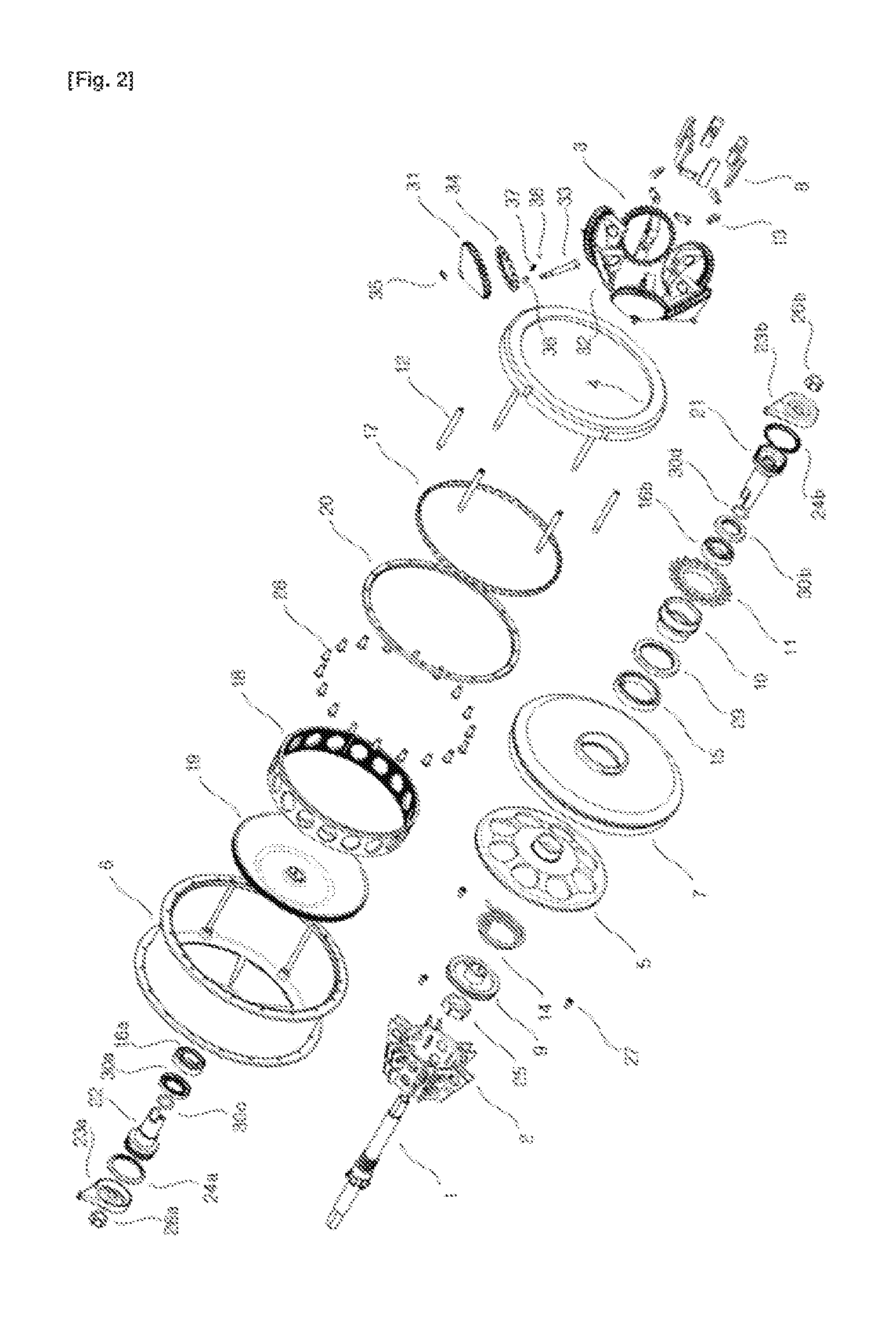
Continuously variable transmission
a transmission and variable technology, applied in mechanical equipment, transportation and packaging, gearing, etc., can solve the problems of low power density and power transmission efficiency, difficult to be put to practical use, and generating a lot of hea
- Summary
- Abstract
- Description
- Claims
- Application Information
AI Technical Summary
Benefits of technology
Problems solved by technology
Method used
Image

Examples
Embodiment Construction
[0034]Terms or words used in the specification and claims should not be limitedly interpreted as normal or lexical meanings, but should be interpreted as meanings and concepts coinciding to technical concepts of the present invention based on the principle that inventors may properly define the concepts of the terms in order to explain their inventions in a best way.
[0035]Therefore, examples described in the specification and constructions illustrated in the drawings are only most preferred example of the present invention, and do not represent all of the technical concepts of the present invention, and thus it should be understood that various equalities and modifications may be present which can replace them at the time of application of the present invention.
[0036]Herein, the term “axial direction” is used to refer to a direction or position along an axis parallel to a central shaft of a transmission or a central shaft of a support member. The term “radial direction” is used to r...
PUM
 Abstract
Description
Claims
Application Information
 - R&D Engineer
- R&D Manager
- IP Professional
- Industry Leading Data Capabilities
- Powerful AI technology
- Patent DNA Extraction
Browse by: Latest US Patents, China's latest patents, Technical Efficacy Thesaurus, Application Domain, Technology Topic, Popular Technical Reports.
© 2024 PatSnap. All rights reserved.Legal|Privacy policy|Modern Slavery Act Transparency Statement|Sitemap|About US| Contact US: help@patsnap.com