Stent Delivery Device

Active Publication Date: 2011-12-08
CR BARD INC
View PDF2 Cites 11 Cited by
  • Summary
  • Abstract
  • Description
  • Claims
  • Application Information

AI Technical Summary

Benefits of technology

[0025]In one preferred embodiment, at least a portion of the pull member is a polymer thread. Such a thread will offer an appropriate amount of flexibility and also allows a reduced profile construction. Preferably, the polymer thread is a polyamide thread. The thread is to have a tear strength sufficient to remain intact while the restraining sheath splits at the line of weakness.
[0026]Preferably, the pull member comprises a stiffer portion attached to the polymer thread portion at a position proximal of the stent device. For example, the proximal portion could b

Problems solved by technology

If perforations are used, the perforations may be of any appropriate density and length and may not necessarily extend all the way through the thickness of the restraining sheath, but m

Method used


Image

  • Stent Delivery Device
  • Stent Delivery Device
  • Stent Delivery Device

Examples


first embodiment

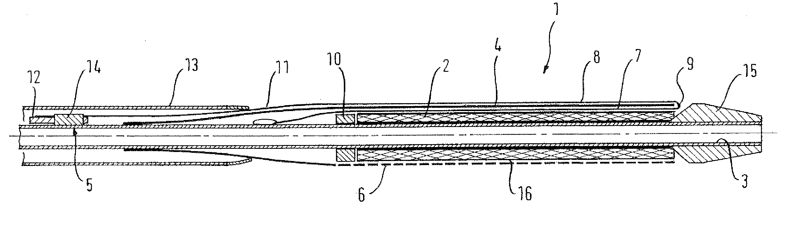
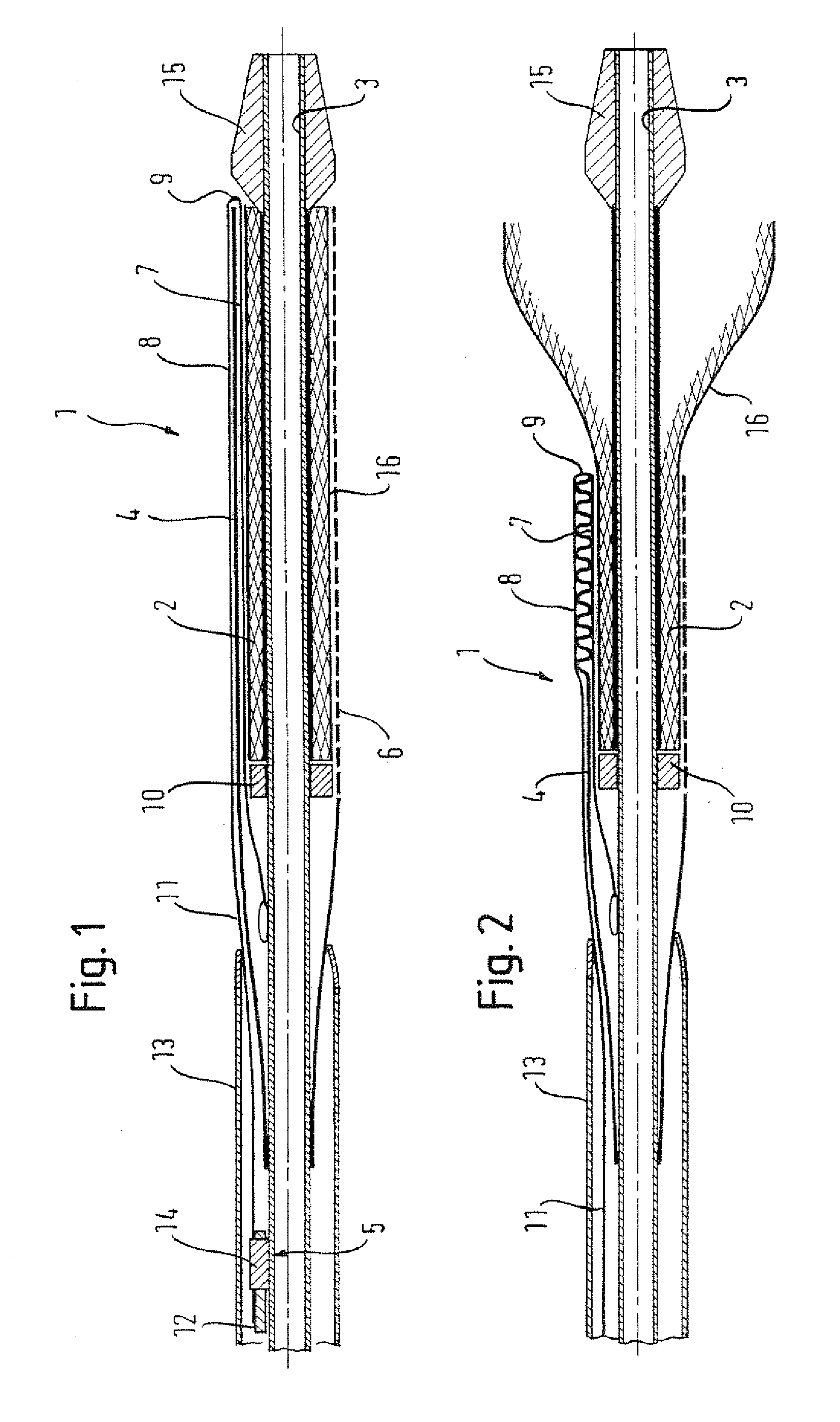
[0064]As in the first embodiment, the line of weakness 6 is located diametrically opposite to the pull member 5.

[0065]The introducer member 13 and the hook 18 are arranged so that as the hook 18 passes the distal end thereof, the hook 18 is unfolded or opened by the distal end wall of the introducer member 13. This ensures that introducer member 13 can maintain a reduced profile.

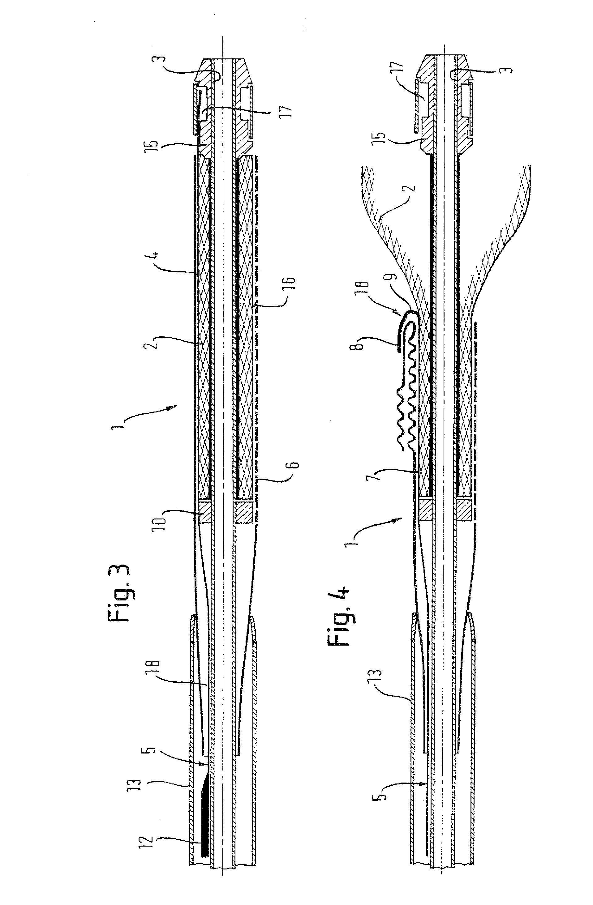
[0066]A method of releasing the stent device 2 from the restraining sheath 4 will now be described. The pull end of the pull member 5 is pulled proximally in order to move the distal end of the pull member 5 out of the storage recess 17 of the distal tip member 15 attached to the inner member 3. The distal end is stored in the storage recess 17 in a collapsed hook form. Once the collapsed hook 18 moves past a restraining wall of the storage recess 17, the hook 18 radially expands.

[0067]The hook 18 proper is continued to be moved proximally by pulling on the pull member 5 and the restraining sheath 4 is engag...

second embodiment

[0091]For example, one can imagine the hook 18 of the second embodiment would not necessarily need to be upwardly facing. The distal end of the pull member 5 forming the short part of the hook 18 could face inwardly towards the stent device 2. One can also envisage this inwardly facing hook 18 being positioned between the stent device 2 and the restraining sheath 4 and the remainder of the pull member 5 being outside of the restraining sheath 4. The hook 18 would thus be tucked into the restraining sheath 4 at the distal end in the delivery configuration, thereby offering a protective mechanism against the projection of the hook 18 damaging tissue. The storage recess 17 could thus be done away with.

[0092]One can also envisage a modification whereby the restraining sheath 4 is withdrawn distally rather than proximally as in the preferred embodiments. This modification has the pull member 5 extending through the lumen of the inner member 3 and out of the distal end of the delivery dev...


PUM


Abstract

A delivery device is provided for delivering a stent device. The stent device (2) is radially expandable from a radially reduced, delivery configuration to a radially expanded, deployment configuration. A restraining sheath (4) is mounted coaxially over the stent device for maintaining the stent device in the delivery configuration. The restraining sheath has a line of weakness (6) extending axially therealong. A pull member is provided, which is to be pulled so as to split the restraining sheath at the line of weakness and withdraw the restraining sheath from over the stent device. The pull member and the line of weakness are located on opposing sides of the restraining sheath. The pull member (5) is wrapped around a distal end of the restraining sheath. The wrap around portion may be formed by a hook of a metal pull member. The wrap around portion may be formed by an open loop of polymer thread. Both ends of the open loop may extend proximally from the restraining sheath and the stent device with one of the ends being fixed to the delivery device and the other being moveable to provide a pull end.

Description

FIELD OF THE INVENTION[0001]The present invention is concerned with a delivery device for releasing a stent device from a restraining sheath in order to deliver the stent device to a treatment site within a patient. The stent device is radially contained within the restraining sheath in a radially reduced, delivery configuration. The restraining sheath has to be released in order that the stent device can be radially expanded into a deployed configuration for holding open a bodily lumen.BACKGROUND OF THE INVENTION[0002]Stent devices are used in the treatment of diseased human or animal bodily lumens to provide structural support to the lumens. Of particular relevance to the present invention are stent devices for supporting and holding open vasculature lumens of the human body.[0003]In order for the stent devices to reach the treatment site, a delivery device is used that passes through vascular passageways, often traversing relatively long and tortuous paths. Surgical procedures fo...

Claims


Application Information

Patent Timeline
IPC IPC(8): A61F2/84A61F2/95A61F2/97
CPCA61F2/95A61F2002/9522A61F2002/9511A61F2/97A61F2230/0069A61F2/9522
Inventor DORN, JURGENHOFFMAN, MARTINADIETRICH, DANIEL
Owner CR BARD INC
Why Eureka
Try Eureka