Method for operating a transmission with at least one positive-locking shifting element

Active Publication Date: 2011-12-08
ZF FRIEDRICHSHAFEN AG
View PDF4 Cites 10 Cited by
  • Summary
  • Abstract
  • Description
  • Claims
  • Application Information

AI Technical Summary

Benefits of technology

[0012]Accordingly, the purpose of the present invention is to provide a method for operating a transmission with at least one positive-locking shifting element, by means of which a positive-locking shifting element involved in a shifting operation can be actuated without additional mechanical synchronization, with reproducibly high shifting quality, within predefined shifting times to the desired extent.
[0015]With the procedure according to the invention, particularly during powershifts, in each case an engagement or closing of a purely positive-locking shifting element without additional mechanical synchronization means, in a simple manner, with high shifting quality and within predefined shifting times, is ensured. This results from the fact that when there is a tooth-on-tooth position in the area of tooth profiles of a purely positive-locking shifting element, which prevents immediate engagement of a shift element and formation of the positive-lock, in a simple manner the tooth-on-tooth position can be released by changing, preferably reducing, the actuation force to a release level of the actuation force, at which a rotational speed difference larger than a second speed difference threshold value is produced between the shift element halves of the positive-locking shifting element, without additional mechanical synchronization, within defined shifting times and with reproducible shifting quality, so that the desired positive-lock is produced.
[0016]When a positive-locking shifting element is actuated with an actuation force at the release level, the friction in the area of the front faces of the tooth profiles between the shift element halves is reduced, at least for a short time, whereby a rotational speed difference between the shift element halves increases and the frictional connection between the shift element halves that exists due to the tooth-on-tooth position is released in a controlled manner. In this way an uncontrolled, abrupt release of the tooth-on-tooth position which would spoil the shifting quality is avoided in a simple, inexpensive and space-saving manner. In addition shift operations, preferably powershifts, during which in each case an positive-locking shifting element has to be engaged, can be carried out within predefined shifting times by virtue of the procedure according to the invention, since the closing time of an positive-locking shifting element can be reproduced exactly and reliably by the controlled release of a tooth-on-tooth position.
[0019]If the actuation force is changed to the release level along a ramp, the system behavior of the positive-locking shifting element is more sensitive, i.e. a tooth-on-tooth position can be released with greater sensitivity than when the actuation force is changed abruptly, and this in turn has a positive effect on the shifting quality.
[0020]In further advantageous variants of the method according to the invention, when a release of a tooth-on-tooth position in the area of the positive-locking shifting element has been detected, the actuation force is changed abruptly or along a ramp to a closing level that engages the positive-locking shifting element, and in doing this the shifting quality can be controlled with greater sensitivity by changing the actuation force along a ramp than by an abrupt change thereof, which again has a positive effect on shifting quality.

Problems solved by technology

A disadvantage of this, however, is that the mechanical synchronizers, provided for synchronizing positive-locking shifting elements, take up considerable structural space and are characterized by substantial complexity of design as well as control and regulation.

Method used


Image

  • Method for operating a transmission with at least one positive-locking shifting element
  • Method for operating a transmission with at least one positive-locking shifting element
  • Method for operating a transmission with at least one positive-locking shifting element

Examples


Embodiment Construction

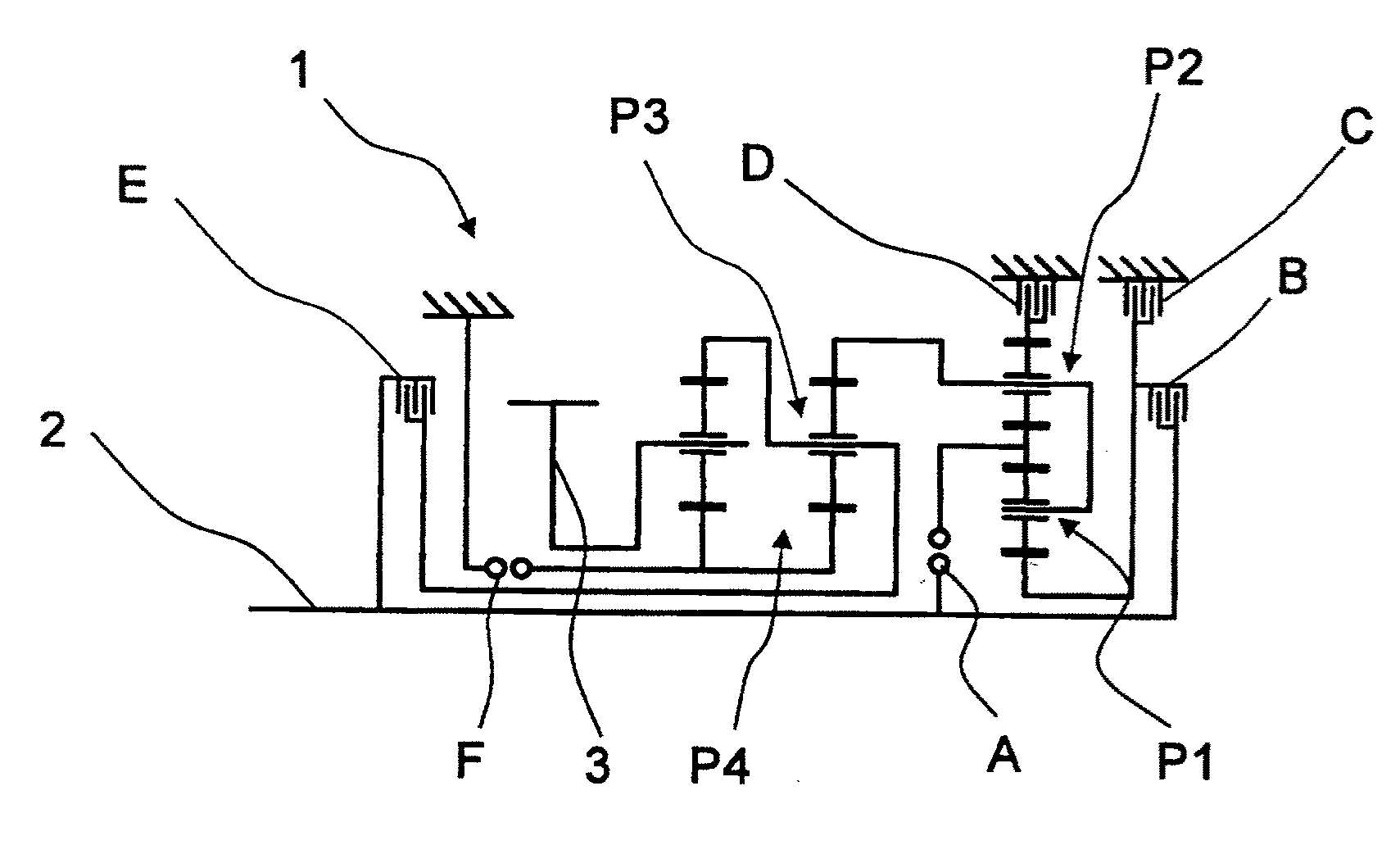
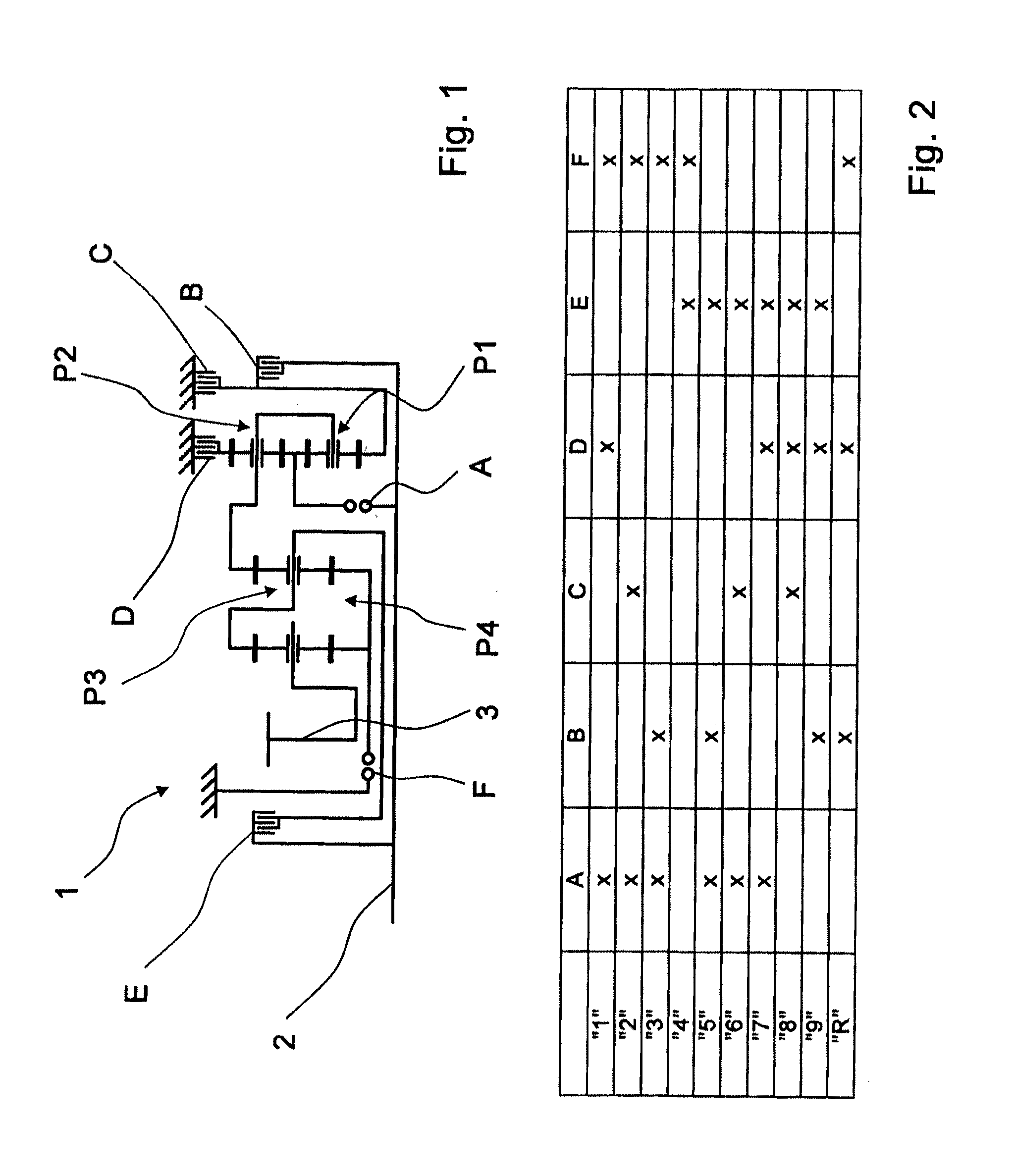
[0030]FIG. 1 shows a gearwheel layout of a transmission 1 or multi-stage transmission, which is basically known from the unpublished German patent application DE 10 2008 000 429.4 by the present applicant. The transmission 1 comprises a driveshaft 2 and an output shaft 3, which when fitted in a vehicle is connected to a drive output of the vehicle whereas the driveshaft 2 is actively connected to a drive machine.

[0031]In addition the transmission 1 is constructed with four planetary gearsets P1 to P4, such that the first and second planetary gearsets P1, P2, which are preferably in the form of minus planetary gearsets, form a shiftable upstream gearset while the third and fourth planetary gearsets P3, P4 constitute the main gearset. Furthermore, the transmission 1 comprises six shift elements A to F, of which the shift elements C, D, and F are brakes and the shift elements A, B and E are designed as shifting clutches.

[0032]With the shift elements A to F, in accordance with the shift...


PUM


Abstract

A method of operating a transmission (1) with at least one interlocking shift element (F) having at least two shift element halves that can be brought into interlocked engagement with one another. When a command is received to close the interlocking shift element (F), a current rotational speed difference between the shift element halves of the interlocking shift element (F) and the current positions of the shift element halves are determined. If the rotational speed difference is smaller than a first speed difference threshold value and if a tooth-on-tooth position has occurred at the interlocking shift element (F), then to release the tooth-on-tooth position, the actuation force is changed to a release level at which a rotational speed difference above a second speed difference threshold value is produced between the shift element halves.

Description

[0001]This application is a National Stage completion of PCT / EP2010 / 054312 filed Mar. 31, 2010, which claims priority from German patent application Ser. No. 10 2009 002 205.8 filed Apr. 6, 2009.FIELD OF THE INVENTION[0002]The invention concerns a method for operating a transmission with at least one positive-locking shifting.BACKGROUND OF THE INVENTION[0003]A shifting device for connecting components of a transmission that are rotating at different speeds, is known from DE 197 56 637 A1. For each shifting group of a range-change transmission, a unit is provided in the shifting device, in which valves, a shifting cylinder, a piston and shift elements are combined. Pulsed 2 / 2-way valves are used as release valves. In addition, in each case a displacement measuring device is provided, by means of which the current position of a piston in relation to a shifting cylinder can be indicated. Thus, when gearwheels are engaged in torque-transmitting connection, the possibility exists of adap...

Claims


Application Information

Patent Timeline
IPC IPC(8): F16H59/38
CPCF16H61/0403F16H61/686F16H2200/2094F16H2200/2064F16H2061/047F16H61/04
Inventor ARNOLD, JORGHERBETH, VALENTINEMIHATSCH, GEORG
Owner ZF FRIEDRICHSHAFEN AG
Why Eureka
Try Eureka