
Electric tool and controlling method thereof

Inactive Publication Date: 2011-12-15
POSITEC POWER TOOLS (SUZHOU) CO LTD
View PDF10 Cites 37 Cited by
  • Summary
  • Abstract
  • Description
  • Claims
  • Application Information

AI Technical Summary

Benefits of technology

[0011]The method automatically detects whether the work piece operated by the tool bit reaches a predetermined position by electronic control means. It may make sure that a screw is driven into a piece of wood and does not go beyond the predetermined position once it detects that the work piece reaches the position and carries out the changing action. There is no complicated mechanical clutch so that it is simple to be made and the cost is decreased.

Problems solved by technology

Thus, the screw may not go too deeply into the piece of wood what it undesirable.
However, the above mechanical clutch is complex in structure and it is complicated and costly to be made.

Method used


Image

  • Electric tool and controlling method thereof
  • Electric tool and controlling method thereof
  • Electric tool and controlling method thereof

Examples


second embodiment

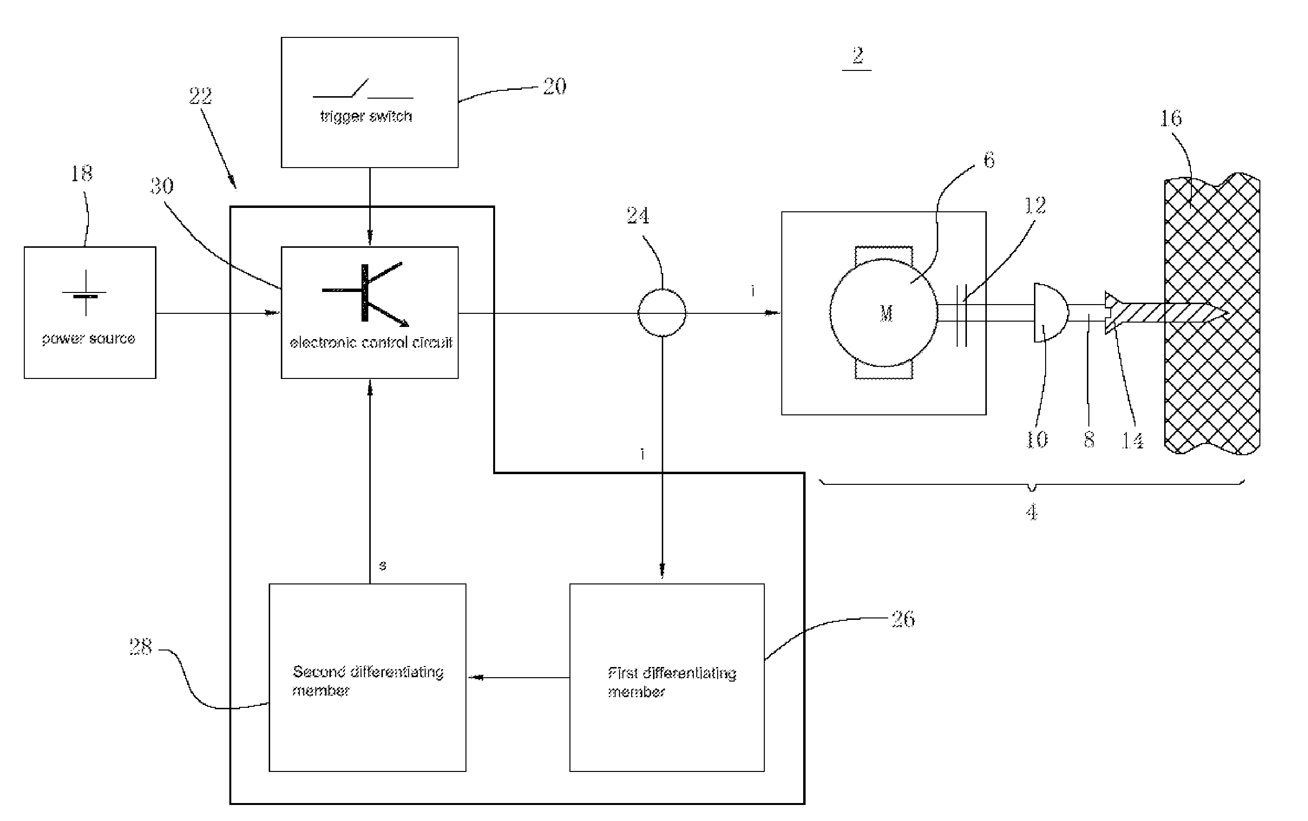
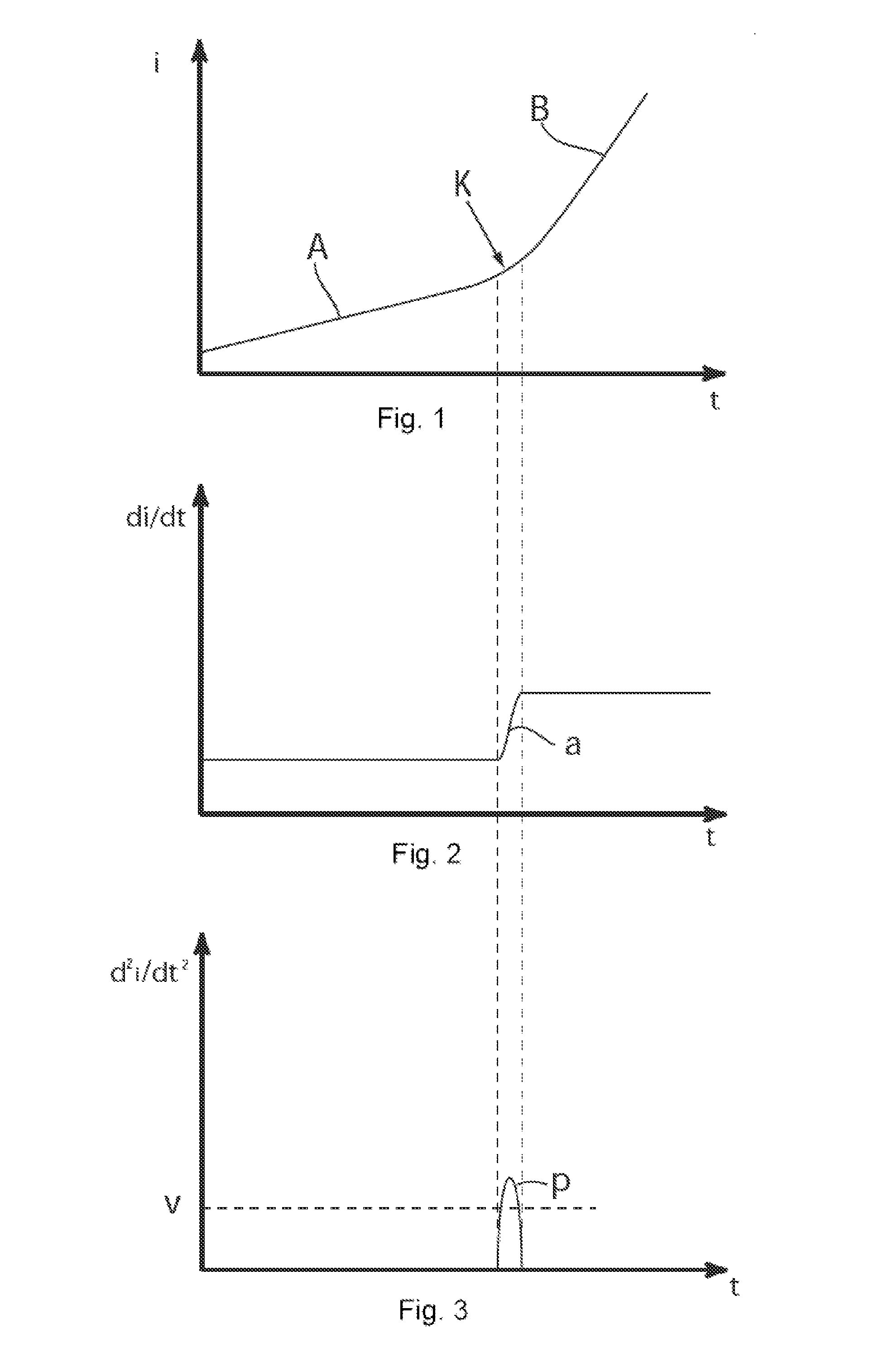
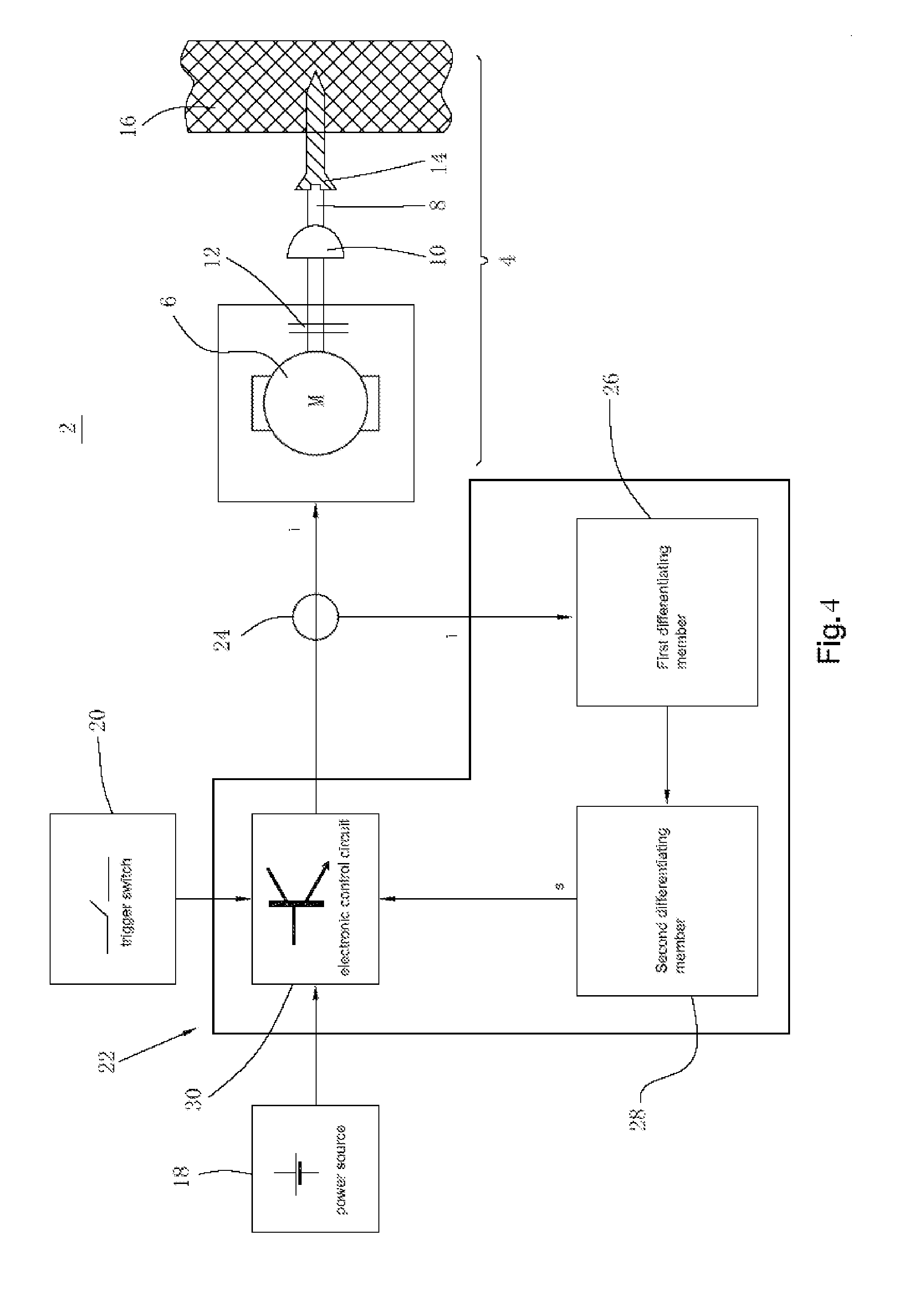
[0057]This may also apply to the If the working head is a very big screw and / or the work-piece is specifically hard, a third threshold value P3 (shown in FIG. 5) and a third predetermined derivative value q3 (shown in FIG. 6) which stored therein will be used in the microprocessor. It should be mentioned that then the set of predetermined threshold values P1, P2 and P3 as well as the predetermined derivative values q1, q2 and q3 is stored in the microprocessor for being individually called upon a request in accordance with the measured current i1, i2, and i3, respectively, at a predetermined point of time T1. Of course, even more sets of predetermined threshold values P and predetermined derivative values q may be used.

[0058]With a number of tests, (e. g. with different screws in specification and different kinds of wood in material and specification), the predetermined threshold values P and the predetermined derivative values q should be determined and stored in the microprocesso...

first embodiment

[0062]The storage and processing unit 32 has stored therein, according to the afore-mentioned first embodiment, a single threshold value P1 and a first and second predetermined derivative value q1 and q2, respectively. At a predetermined point of time T1, the storage and processing unit 32 selects the first predetermined derivative value q1, if the measured current i1 is below the threshold value P1, or it selects the second predetermined derivative value q2, if the measured current i2 is above the threshold value P1. The second predetermined derivative value q2 is larger than the first predetermined derivative value q1. The storage and processing unit 32 also generates a corresponding control signal s1 or s2, when the first derivative di / dt has reached the first or second predetermined derivative value q1, q2. Here the screw head has reached the piece of wood. And the storage and processing unit 32 supplies the control signal s1 or s2 to the electronic control device 22. This contr...


PUM


Abstract

A power tool including a motor for rotatably driving a tool bit at an attained rotational speed, a source for supplying an electric current to the motor, a sensor for measuring the current, and a control device. The control component fulfils the task of detecting a variation of the slope of the current in the course of time, and generates a control signal. The rotational speed of the tool is reduced in response to the control signal. The power tool automatically detects whether the work piece operated by the tool bit reaches a predetermined position by electronic control means. It may make sure that the screw is driven into a piece of wood and does not go beyond the predetermined position once it detects that the work piece reaches the position and carries out a changing action.

Description

CROSS-REFERENCES TO RELATED APPLICATIONS[0001]The instant application claims priority to and all the benefits of International Application No. PCT / CN2010 / 070014 filed Jan. 4, 2010, with the World Intellectual Property Organization, and which claims priority to Chinese Application No. CN200910001862.5 filed Jan. 4, 2009.BACKGROUND OF THE INVENTION[0002]1. Field of the Invention[0003]The invention relates to an electric tool, preferably an electric screw driver, and a controlling method of the electric tool.[0004]2. Description of the Related Art[0005]In the present power tools, such as electric screw drivers, which is driven by a rotary motor and screw into a board of wood via supplying current from a loaded power. The screws may have different diameters. And the shapes of the heads of different screws are different from each other. Thus different circumstance will occur when different screws are driven into the same board of wood. Additionally, if the same screw is driven into diffe...

Claims


Application Information

Patent Timeline
IPC IPC(8): B25B23/00B23Q5/04
CPCB23P19/066B25B23/14B25B23/147H02P29/02H02P3/08H02P7/285H02P7/29G05D17/02
Inventor TANG, XIANGYANG
Owner POSITEC POWER TOOLS (SUZHOU) CO LTD
Features
  • Generate Ideas
  • Intellectual Property
  • Life Sciences
  • Materials
  • Tech Scout
  • Unparalleled Data Quality
  • Higher Quality Content
  • 60% Fewer Hallucinations
Learn More