Silencer for an auxiliary power unit of an aircraft

Active Publication Date: 2011-12-15
AIRBUS OPERATIONS GMBH
View PDF12 Cites 6 Cited by
  • Summary
  • Abstract
  • Description
  • Claims
  • Application Information

AI Technical Summary

Benefits of technology

[0012]Exhaust gas entering the flow channel through an inlet flows toward an outlet within the flow channel and is discharged into the surroundings of the aircraft at this location. The wall material of the silencer according to the invention is porous—as it is also known from the state of the art—and allows an alternating flow through a wall of the flow channel. While flowing through the porous wall material, part of the sound energy is converted into heat such that a certain noise reduction takes place. The cells distributed along the silencer according to the invention cause this noise reduction to repeat several times such that adequate sound dampening can be achieved.
[0050]According to another advantageous additional improvement of the silencer according to the invention, the annular channel is open on an inner circumference, i.e., on the surface that is directed toward the center of the annular channel, wherein this inner circumference is placed on the outlet of the silencer. The individual openings that connect the annular channel to the outlet therefore are only produced in the outlet itself such that the production costs for manufacturing the annular channel are lowered and its weight is reduced due to a smaller material quantity.

Problems solved by technology

One problem of known silencers of this design is, for example, an insufficient ratio between the diameter of the flow channel and of the housing such that, for example, the outer diameter of the cells is relatively low by comparison and, in particular, a first occurring transversal mode of the exhaust gas sound therefore can only be weakly dampened.
However, there are also known silencers, in which the diameter of the housing is sufficient such that the first transversal mode can be dampened sufficiently strong, but not the second transversal mode.
Another disadvantage of these known silencers consequently can be seen in that the sound dampening is very low for certain frequency ranges due to standing waves in the silencer.
In the design of a corresponding silencer, the available installation space is very restricted, particularly in aircraft, such that the external dimensions of the silencer cannot be arbitrarily enlarged in order to increase the degree of sound dampening, but rather should always be maintained constant or at least as small as possible.
In the existing designs of silencers for auxiliary power units of an aircraft, improvements with respect to the degree of sound dampening are not readily expected without enlarging the external dimensions of the silencer.

Method used


Image

  • Silencer for an auxiliary power unit of an aircraft
  • Silencer for an auxiliary power unit of an aircraft
  • Silencer for an auxiliary power unit of an aircraft

Examples


example 1

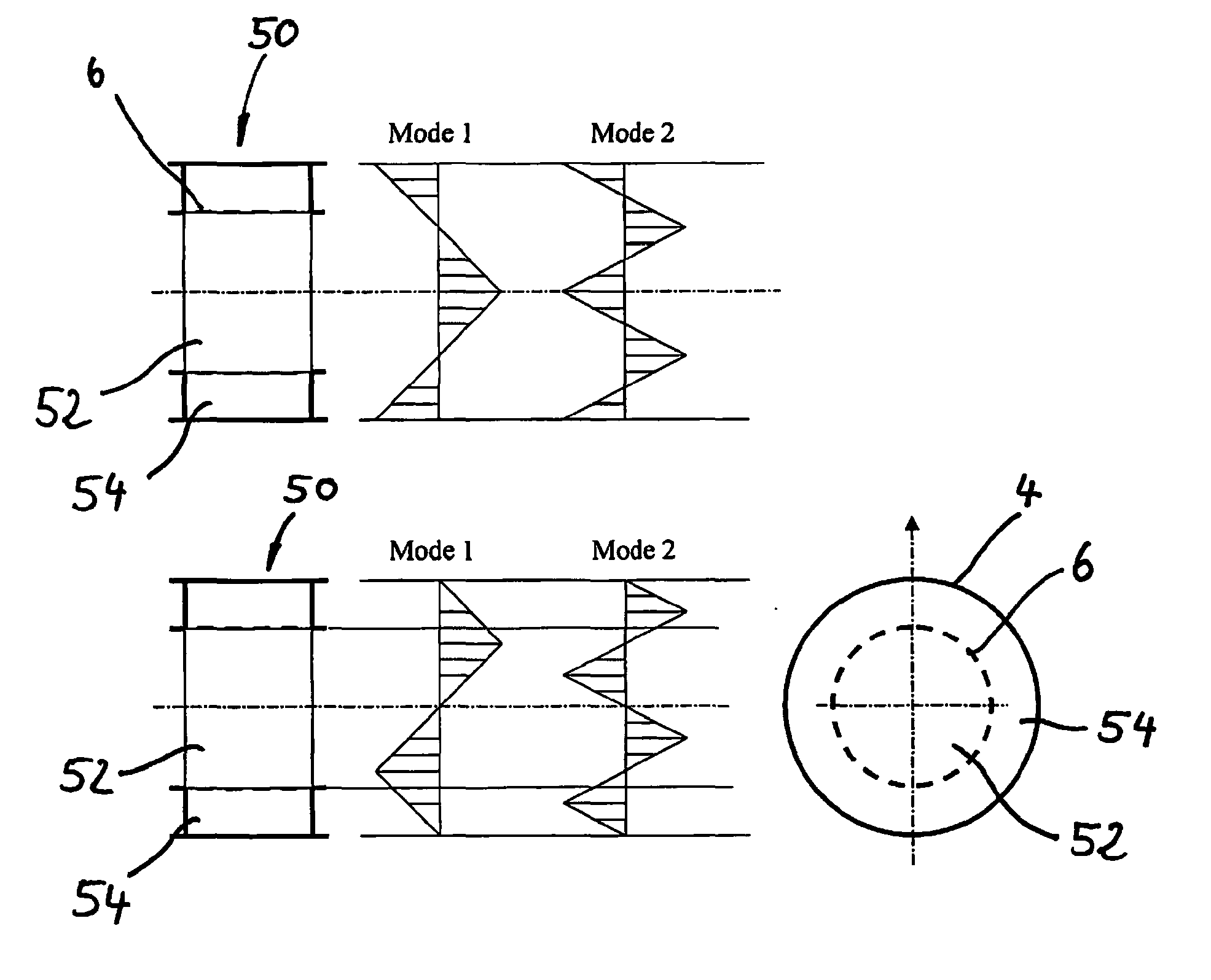
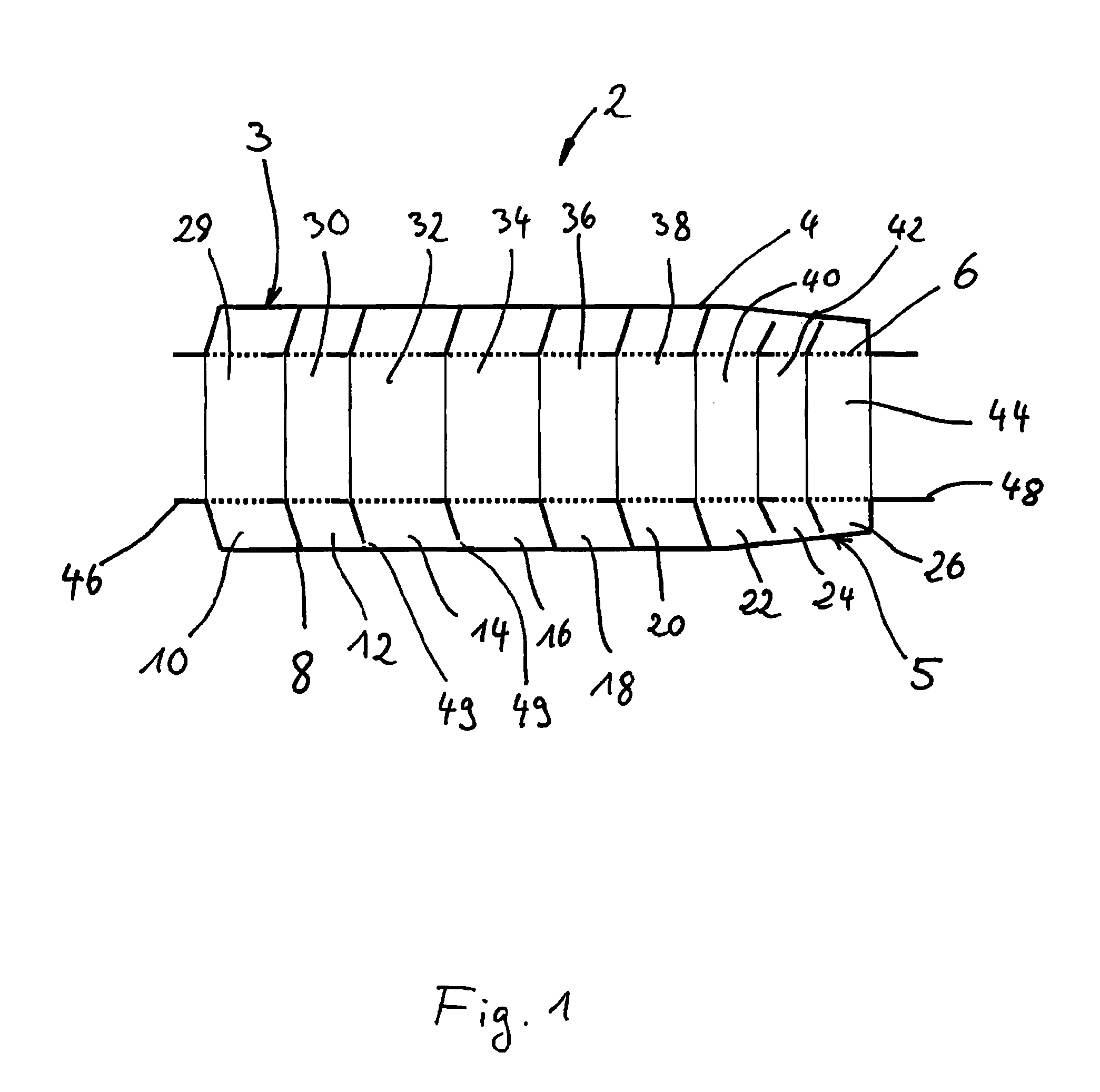
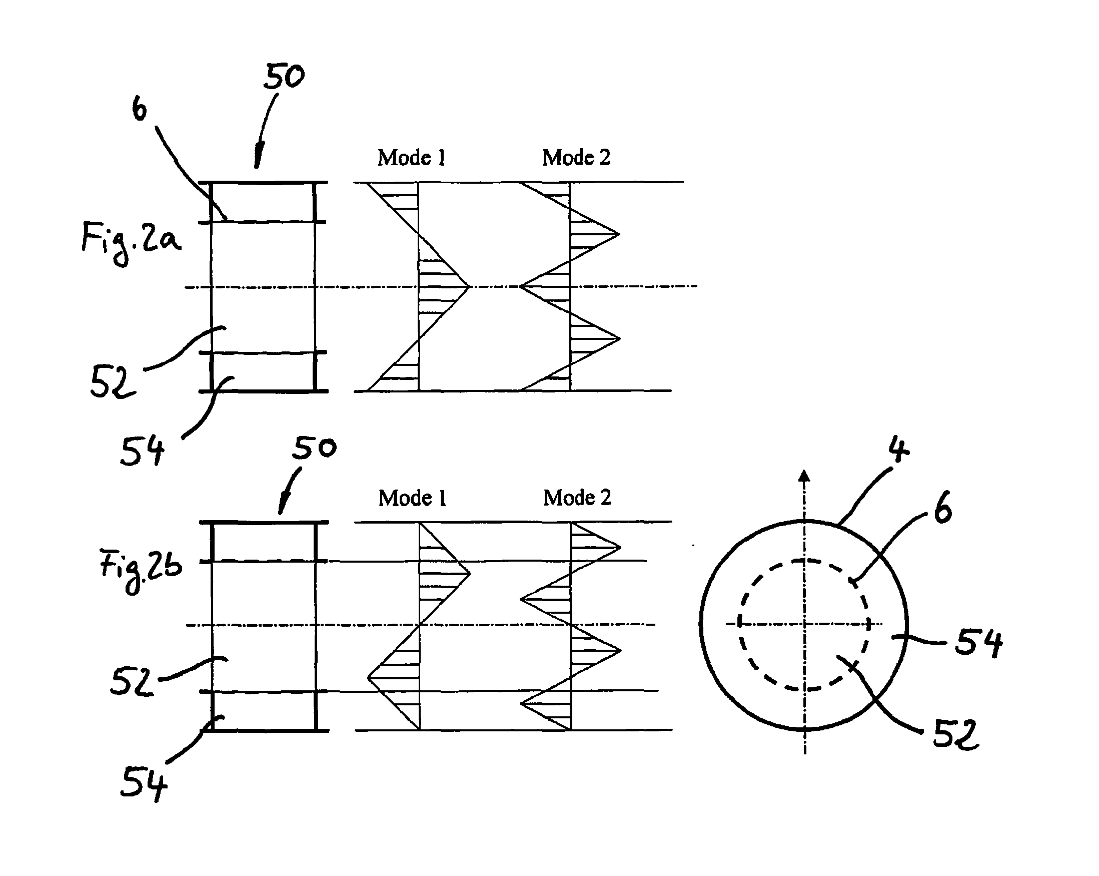
[0115]A silencer for an auxiliary power unit of an aircraft comprises an inlet, an outlet, a housing and a flow channel that is arranged in the housing, wherein an intermediate space formed between the housing and the flow channel is divided into outer cells arranged around the flow channel by means of one or more partitions and the wall material of the flow channel is porous, wherein the partitions are arranged relative to one another in such a way that at least two outer cells with a respective length that corresponds to 0.2-0.6-times the hydraulic diameter of the flow channel and a respective height that corresponds to 0.3-0.45-times the hydraulic diameter of the flow channel are formed in the intermediate space between the housing and the flow channel in a cylindrical section of the housing, wherein at least one outer cell is divided into an outer region and an inner region by means of a porous absorber layer in the cylindrical section of the housing, and wherein the outer regio...

example 2

[0116]A silencer of example 1, in which the housing has a conical shape at least in one section.

example 3

[0117]A silencer of example 1 or 2, in which the sum of the volumes of all outer regions of at least one outer cell in the cylindrical section of the housing corresponds to 0.8-1.2-times the sum of the volumes of all inner regions of the same outer cell.


PUM


Abstract

A silencer for an auxiliary power unit of an aircraft comprises an inlet, an outlet, a housing and a flow channel with a porous wall material that is arranged in the housing. An intermediate space is formed between the housing and the flow channel and divided into outer cells that are arranged around the flow channel by means of one or more partitions. This makes it possible to realize a very compact silencer with very good sound insulation properties. The sound dampening can be additionally improved by dividing the outer cells into outer regions and inner regions, by adapting the shape of the silencer to a tail section of an aircraft and by arranging an annular channel on the outlet.

Description

[0001]REFERENCE TO ASSOCIATED APPLICATIONS[0002]The present application claims the priority of German Patent Application No. 10 2008 051 241.9 submitted on Oct. 10, 2008, U.S. Provisional Application No. 61 / 195,835 submitted on Oct. 10, 2008, German Patent Application No. 10 2009 006 579.2 submitted on Jan. 29, 2009 and U.S. Provisional Application No. 61 / 148,328 submitted on Jan. 29, 2009, wherein the contents of the aforementioned applications are incorporated herein by reference.TECHNICAL FIELD OF THE INVENTION[0003]The invention pertains to a silencer for an auxiliary power unit of an aircraft with a housing and a flow channel arranged in the housing, wherein the intermediate space between the flow channel and the housing is divided into several cells. The invention furthermore pertains to the utilization of a silencer for an auxiliary power unit in an aircraft, as well as to an aircraft with at least one auxiliary power unit and at least one silencer according to the invention....

Claims


Application Information

Patent Timeline
IPC IPC(8): B64C1/40B64D33/04B64D41/00
CPCB64D33/06B64D41/00B64D2033/0213B64D2041/002F05D2220/50F02C7/32F02K1/827Y02T50/44F02C7/24Y02T50/40
Inventor STAROBINSKI, RUDOLFSIERCKE, MATTHIAS
Owner AIRBUS OPERATIONS GMBH
Why Eureka
Try Eureka