Mold for molding resin, apparatus for molding resin, and method for molding resin

Inactive Publication Date: 2011-12-15
TECHNO POLYMER CO LTD
View PDF2 Cites 3 Cited by
  • Summary
  • Abstract
  • Description
  • Claims
  • Application Information

AI Technical Summary

Benefits of technology

[0009]The present invention was devised in view of such existing problems and intends to provide a rubber mold for molding a resin, an apparatus for molding a resin, and a method for molding a resin which can reduce the amount of a rubber material to be used for the production of rubber molds for exchange and can prevent the opening of a rubber mold by a simple structure and thereby afford a molded article made of a thermoplastic resin and stable in dimensional accuracy.Means for Solving the Problems
[0032]By the method for molding a resin of this invention, by the same constitution as that of the aforementioned third invention, it is possible to effectively prevent the opening of the plurality of split mold parts constituting the core mold and, thereby, shorten the molding cycle of molded articles of a thermoplastic resin. Moreover, also in this invention, like the aforementioned third invention, it is possible to prevent the opening of the rubber mold by a simple structure and prevent the thermal degradation of the rubber mold and, thereby, afford a molded article made of a thermoplastic resin and stable in dimensional accuracy.

Problems solved by technology

However, since a mold made of a rubber such as a silicone rubber seriously suffers thermal degradation after its use for molding a thermoplastic resin because it is made of a rubber, its use in several tens shots (moldings) makes it necessary to be exchanged.
Thus, the amount of a rubber material to be used for the production of molds becomes large.

Method used


Image

  • Mold for molding resin, apparatus for molding resin, and method for molding resin
  • Mold for molding resin, apparatus for molding resin, and method for molding resin
  • Mold for molding resin, apparatus for molding resin, and method for molding resin

Examples


examples

[0069]Hereinafter, an example concerning the rubber mold for molding a resin, the apparatus for molding a resin, and the method for molding a resin of the present invention is described with reference to drawings.

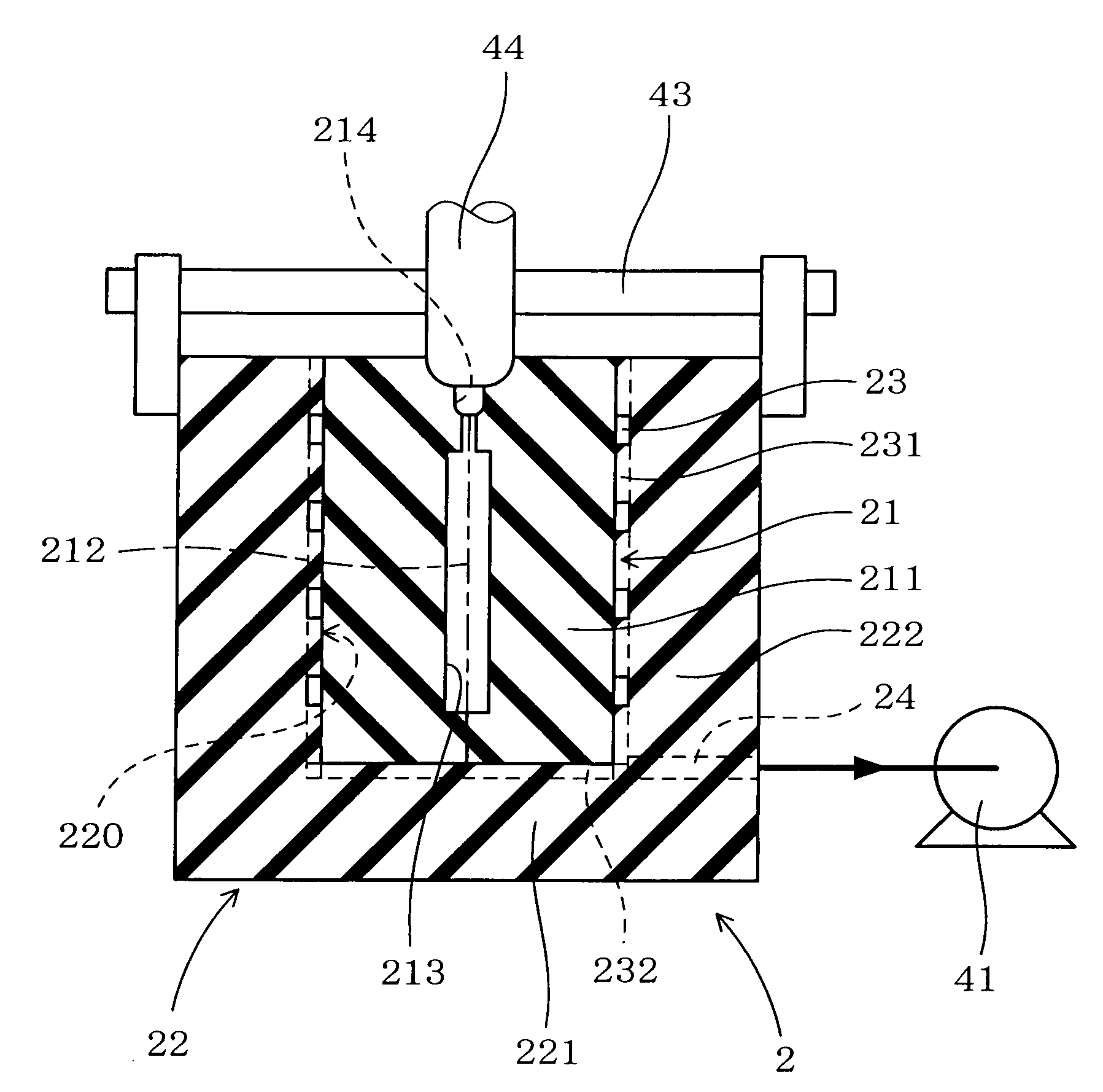
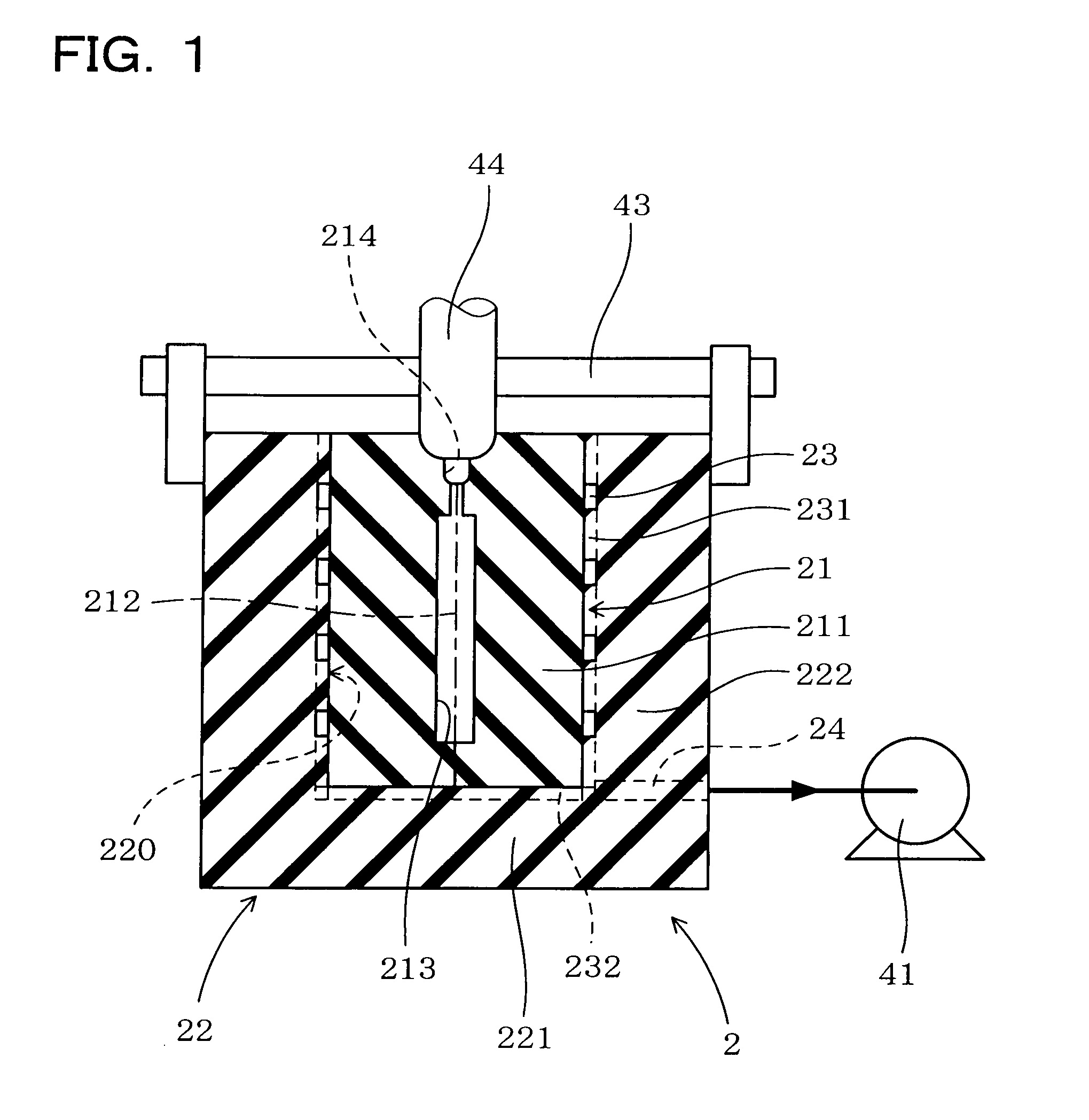
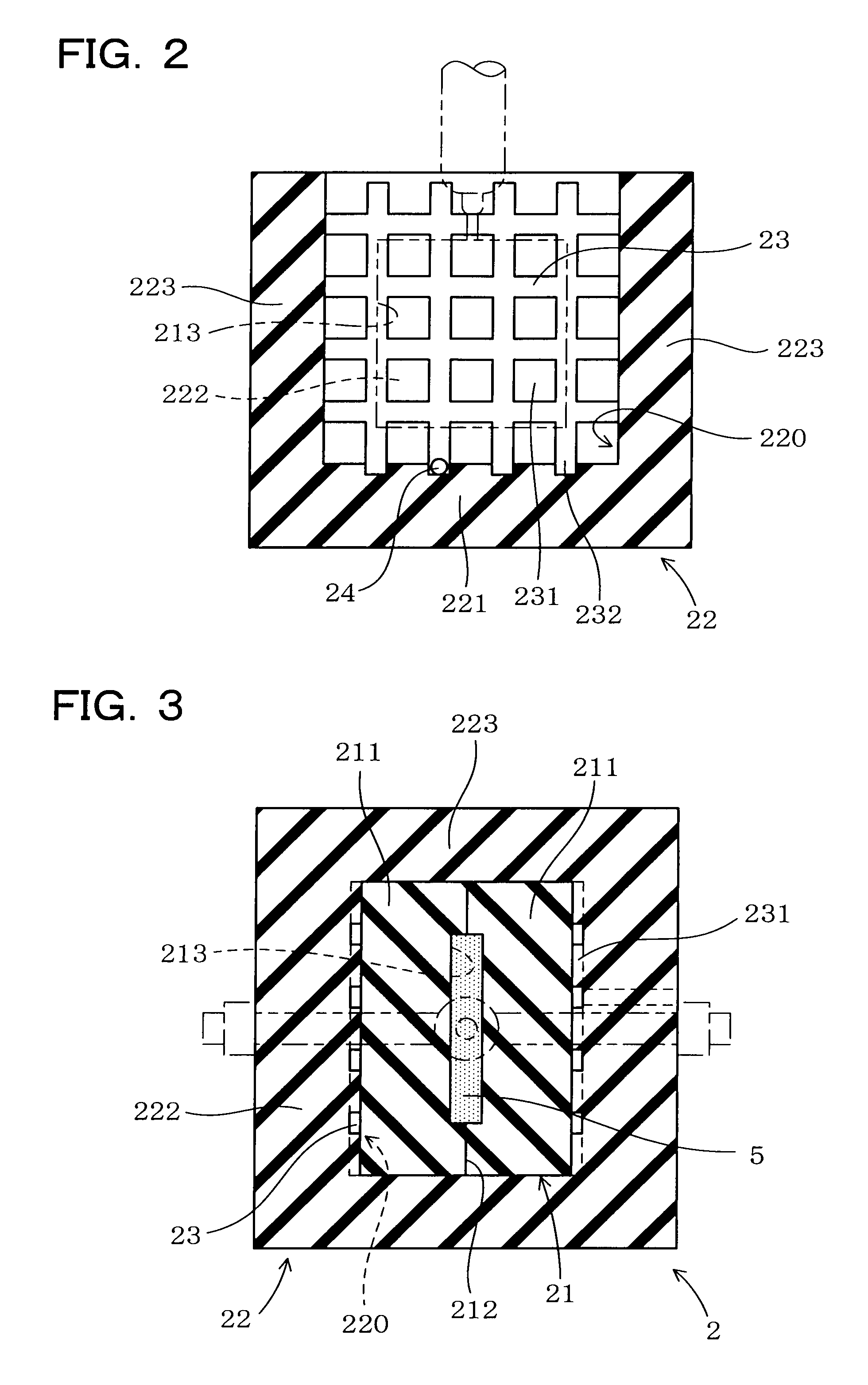
[0070]The rubber mold for molding a resin 2 of this example is provided with a cavity 213 for filling a thermoplastic resin 5 in a molten state thereinto by applying pressure as illustrated in FIG. 1 through FIG. 4. The rubber mold 2 is composed of a core mold 21 being made of a rubber material and provided with the cavity 213, and a base mold 22 being made of a rubber mold and having such a shape that the core mold 211 is to be placed in the inside part 220. The core mold 21 has been formed by combining a plurality of split mold parts 211 (a pair of split mold parts 211 in this example) together on splitting surfaces 212 for opening the cavity 213. The base mold 22 has at least a bottom part 221 and a pair of first side parts 222 standing from two opposite side edges of th...


PUM

PropertyMeasurementUnit
Lengthaaaaaaaaaa
Wavelengthaaaaaaaaaa
Pressureaaaaaaaaaa

Abstract

A rubber mold for molding a resin 2 is provided with a cavity 213 for filling therein a thermoplastic resin in a molten state by applying pressure. The rubber mold 2 includes a core mold 21 made of a rubber material and provided with the cavity 213 and a base mold 22 made of a rubber material and having such a shape that the core mold 21 is to be placed therein. The core mold 21 is formed by combining a pair of split mold parts 211 which is divided on splitting surfaces 212 for opening the cavity 213. The base mold 22 has a bottom part 221 and a pair of first side parts 222 formed on two opposite sides in a direction in which the plurality of split mold parts are aligned with each other.

Description

TECHNICAL FIELD[0001]The present invention relates to a rubber mold for molding a resin, an apparatus for molding a resin, and a method for molding a resin each for obtaining a molded article of a thermoplastic resin.BACKGROUND ART[0002]Methods for obtaining a molded resin article having a prescribed shape using a thermoplastic resin generally include various molding methods, such as injection molding, blow molding, extrusion molding, and press molding.[0003]On the other hand, for example, patent document 1 discloses a method for molding a resin, which is capable of selectively heating a thermoplastic resin through a mold when molding a molded resin article made of a thermoplastic resin by a vacuum molding process using a mold made of rubber such as a silicone rubber (rubber mold). In this method for molding a resin, when filling a molten thermoplastic resin into a cavity of a mold, an electromagnetic wave including a wavelength region of from 0.78 to 2 μm is irradiated to the therm...

Claims


Application Information

Patent Timeline
IPC IPC(8): B29C33/06B29C33/40
CPCB29C33/405B29C35/0888B29C2035/1616B29C37/006B29C2035/0822B29C35/0894
Inventor KURIHARA, FUMIOTAKAMI, MASAMITSU
Owner TECHNO POLYMER CO LTD
Why Eureka
Try Eureka