Touch screen device

Inactive Publication Date: 2011-12-15
PANASONIC CORP
View PDF11 Cites 24 Cited by
  • Summary
  • Abstract
  • Description
  • Claims
  • Application Information

AI Technical Summary

Benefits of technology

[0013]In view of the above-described circumstances, the present invention provides a touch screen device that can performs detection processing of a touch position at high speed, even if the number of electrodes increases, along with an increase in the size of the touch screen device.
[0015]According to an aspect of the present invention, detection data can be transmitted to the system controller, using the time of performing a scanning operation. Accordingly, while a drive signal is applied to the transmission electrode, signals output from the receiving electrodes are processed. Accordingly, the scanning operation does not need to wait for the transmission of detection data, and thus, a processing speed of detecting a touch position can be improved.

Problems solved by technology

Thus, the amount of data necessary to obtain a touch position increases by a large amount.
Such an increase in the amount of data may increase a processing time necessary to detect a touch position, and thus may cause a phenomenon that the processing for detecting a touch position cannot follow a touch operation by a pointing device, such as a finger, or the like.
However, the above described conventional technology cannot reduce the time necessary for data transmission.
Therefore, an amount of data also becomes enormous, and the time necessary for data transmission increases.

Method used


Image

  • Touch screen device
  • Touch screen device
  • Touch screen device

Examples


Embodiment Construction

[0026]The particulars shown herein are by way of example and for purposes of illustrative discussion of the embodiments of the present invention only and are presented in the cause of providing what is believed to be the most useful and readily understood description of the principles and conceptual aspects of the present invention. In this regard, no attempt is made to show structural details of the present invention in more detail than is necessary for the fundamental understanding of the present invention, the description taken with the drawings making apparent to those skilled in the art how the forms of the present invention may be embodied in practice.

[0027]Embodiments of the present invention will be described hereinafter with reference to the drawings.

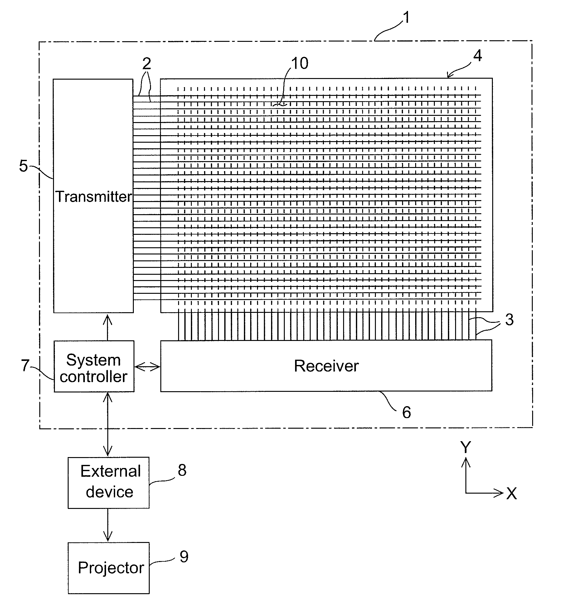
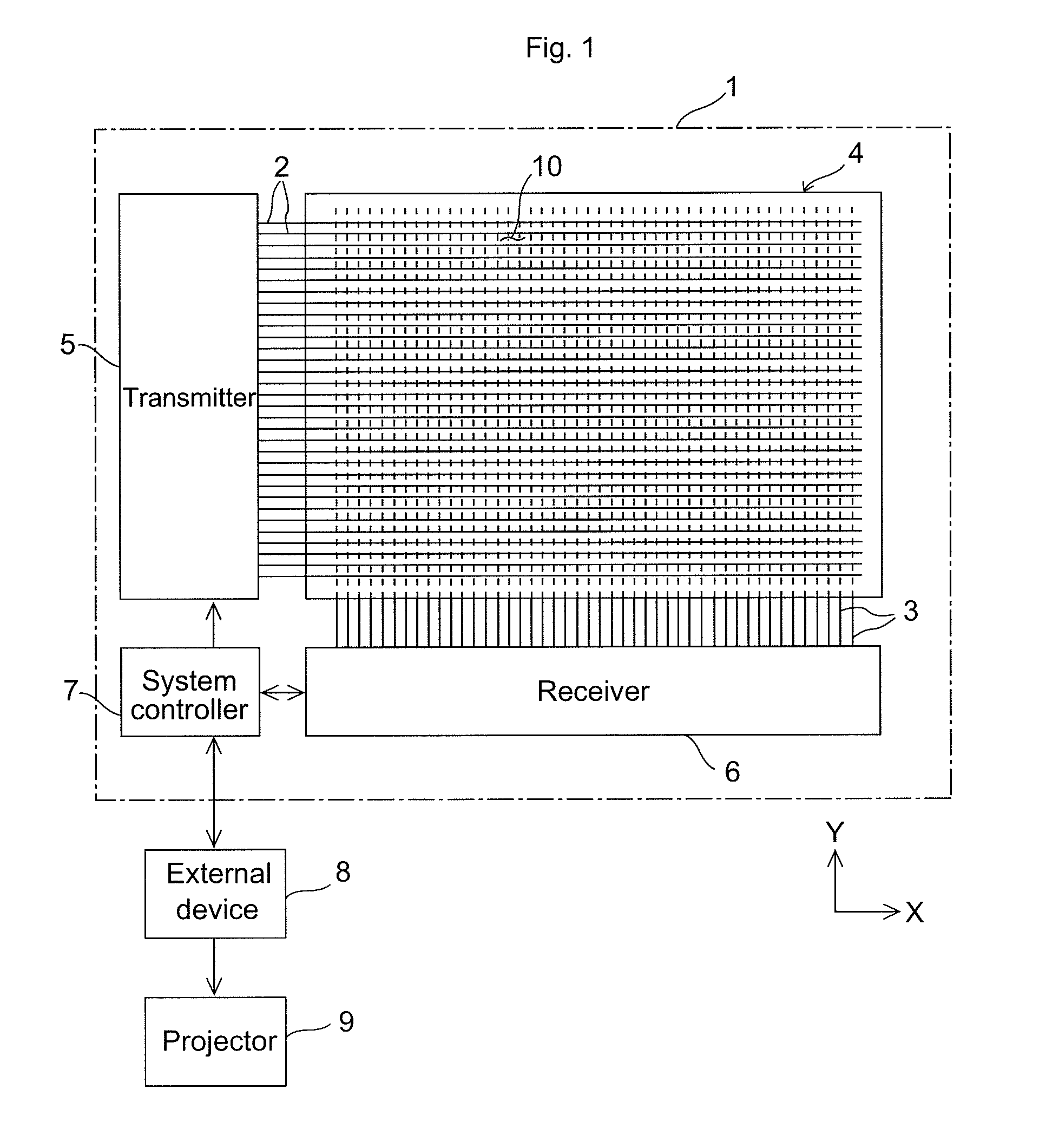
[0028]FIG. 1 is a configuration diagram illustrating an entire touch screen system according to an embodiment of the present invention. The touch screen device 1 includes a panel body 4, in which a plurality of transmission ele...


PUM


Abstract

A touch screen device is provided that includes a receiving signal processor, an odd number line FIFO, an even number line FIFO, and a first selector. The receiving signal processor processes output signals from receiving electrodes and outputs detection data. The odd number line FIFO and the even number line FIFO respectively store the detection data output from the receiving signal processor on a line basis. The first selector alternately selects outputs of the odd number line FIFO and the even number line FIFO. While one of the odd number line FIFO and the even number line FIFO performs writing of the detection data, the other performs reading.

Description

CROSS-REFERENCE TO RELATED APPLICATIONS[0001]The present application claims priority under 35 U.S.C. §119 of Japanese Application No. 2010-134430, filed on Jun. 11, 2010, the disclosure of which is expressly incorporated by reference herein in its entirety.BACKGROUND OF THE INVENTION[0002]1. Field of the Invention[0003]The present invention relates to a capacitive touch screen device that has electrodes arranged in a grid pattern, and detects a touch position based on a variation in an output signal from the electrodes caused by the change in capacitance in response to a touch operation. In particular, the present invention relates to a mutual capacitance touch screen device that detects a touch position by receiving a charge-discharge current signal flowing through a receiving electrode in response to a drive signal applied to a transmission electrode.[0004]2. Description of Related Art[0005]The touch screen device is widely used in fields of personal computers or handheld terminal...

Claims


Application Information

Patent Timeline
IPC IPC(8): G06F3/041
CPCG06F3/044G06F3/0416G06F3/04166G06F3/0446G06F3/0445
Inventor MAEDA, TAKAMIHIRAKAWA, MASAMI
Owner PANASONIC CORP
Why Eureka
Try Eureka