Laser processing apparatus, laser processing method and thin plate processed using the same

Active Publication Date: 2020-07-09
WIRED CO LTD
View PDF0 Cites 1 Cited by
  • Summary
  • Abstract
  • Description
  • Claims
  • Application Information

AI Technical Summary

Benefits of technology

The present invention is related to a laser processing apparatus and method for opening a large number of fine through holes in a thin plate with uniform shape and arrangement. The apparatus includes a cylindrical body with an opening, a thin plate transfer means for transferring a thin plate in the longitudinal direction of the thin plate, a motor with a rotation axis, a reflecting member fixed to a rotating shaft of the motor, and a laser light emitting means for emitting pulsed light. The method involves repeatedly scanning the thin plate with the pulsed light at a high speed in the same direction by one row, and irradiating the thin plate with the pulsed light through the opening. The apparatus and method can improve processing speed and accuracy, and suppress the generation of burrs around the fine through holes. Additionally, a light condensing means can be used to adjust the focal position of the pulsed light, and the apparatus can be used with a continuous thin plate transfer system.

Problems solved by technology

However, in forming through holes in a metal thin plate by etching processing, there has been big problems such as instability in shapes of through holes, large processing cost because of a large number of processes for wet processing, difficulty in forming through holes of 100 μm or less and difficulty in improving the processing speed.
Further, in cases where a thin plate is not a metal thin plate but a plastic or ceramic, there has been a problem that etching processing cannot be adopted.

Method used


Image

  • Laser processing apparatus, laser processing method and thin plate processed using the same
  • Laser processing apparatus, laser processing method and thin plate processed using the same
  • Laser processing apparatus, laser processing method and thin plate processed using the same

Examples


example 1

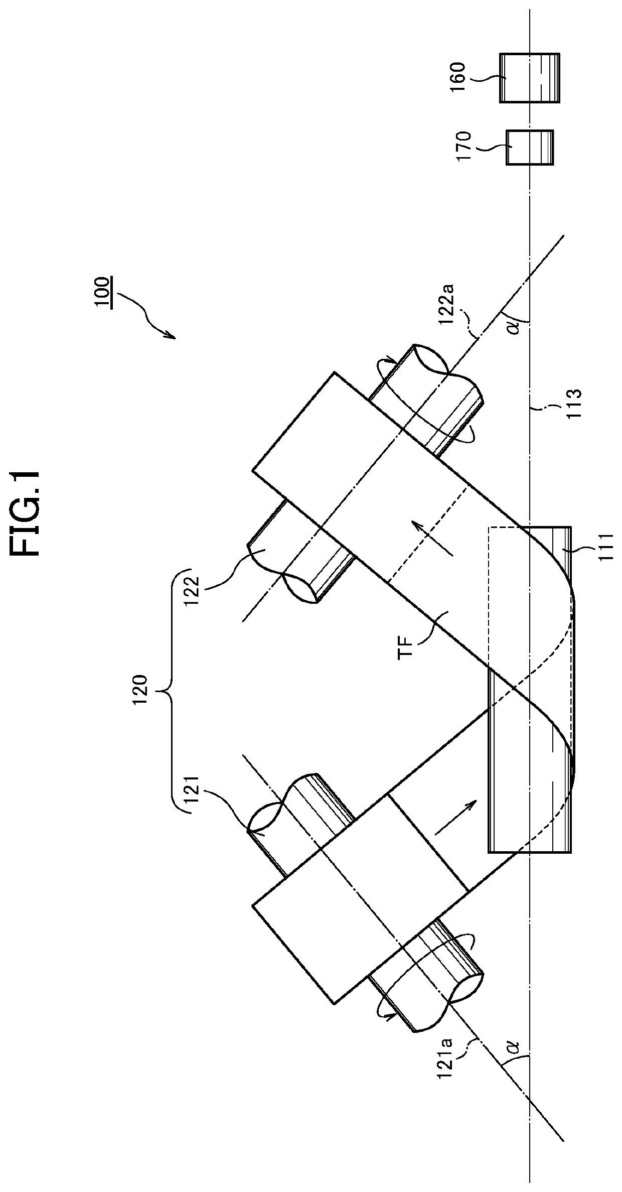
[0122]A laser processing apparatus according to the first example of the present invention will be described below with reference to FIGS. 1 to 6, together with a laser processing method and a laser processed long thin plate material.

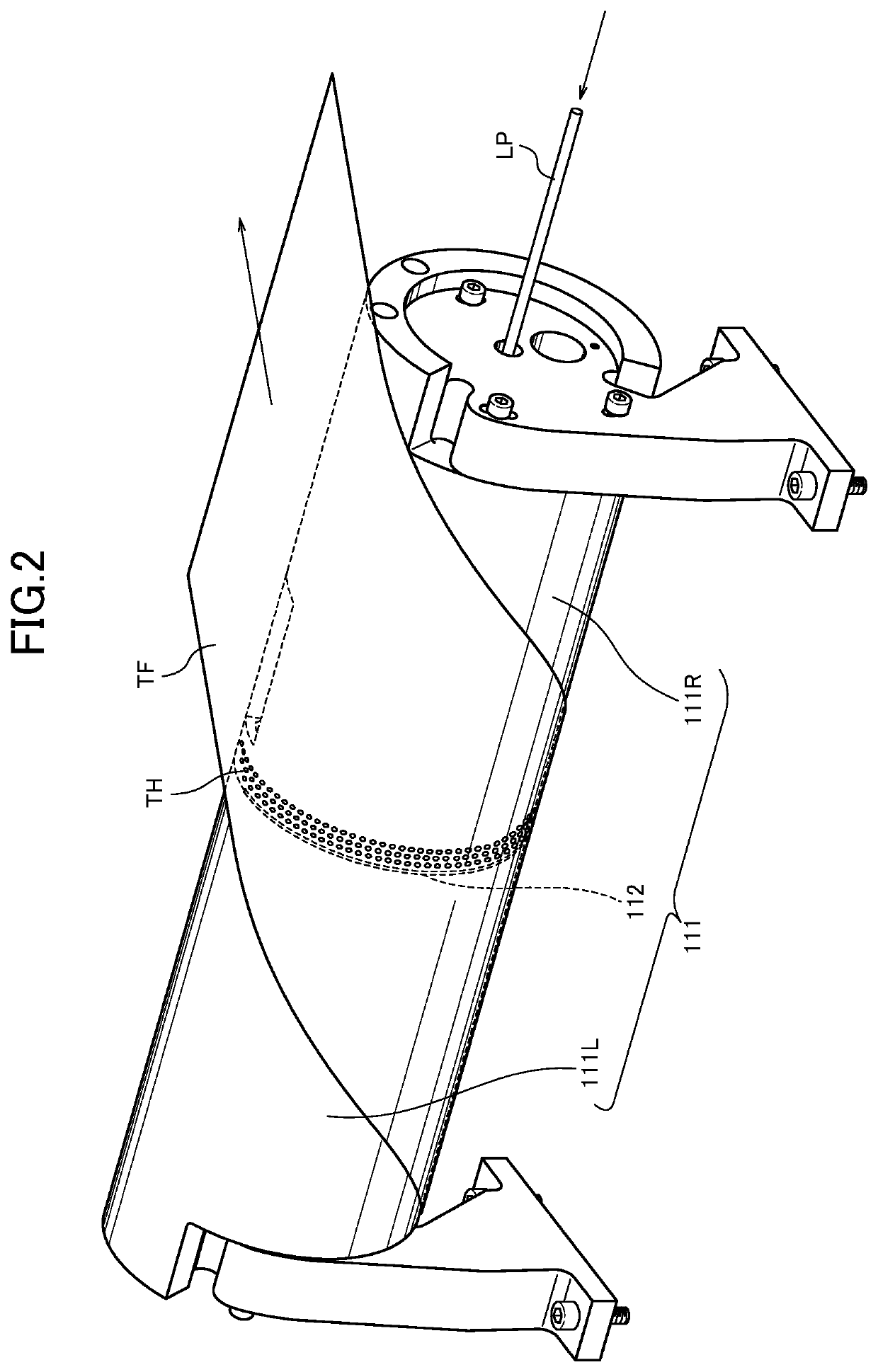
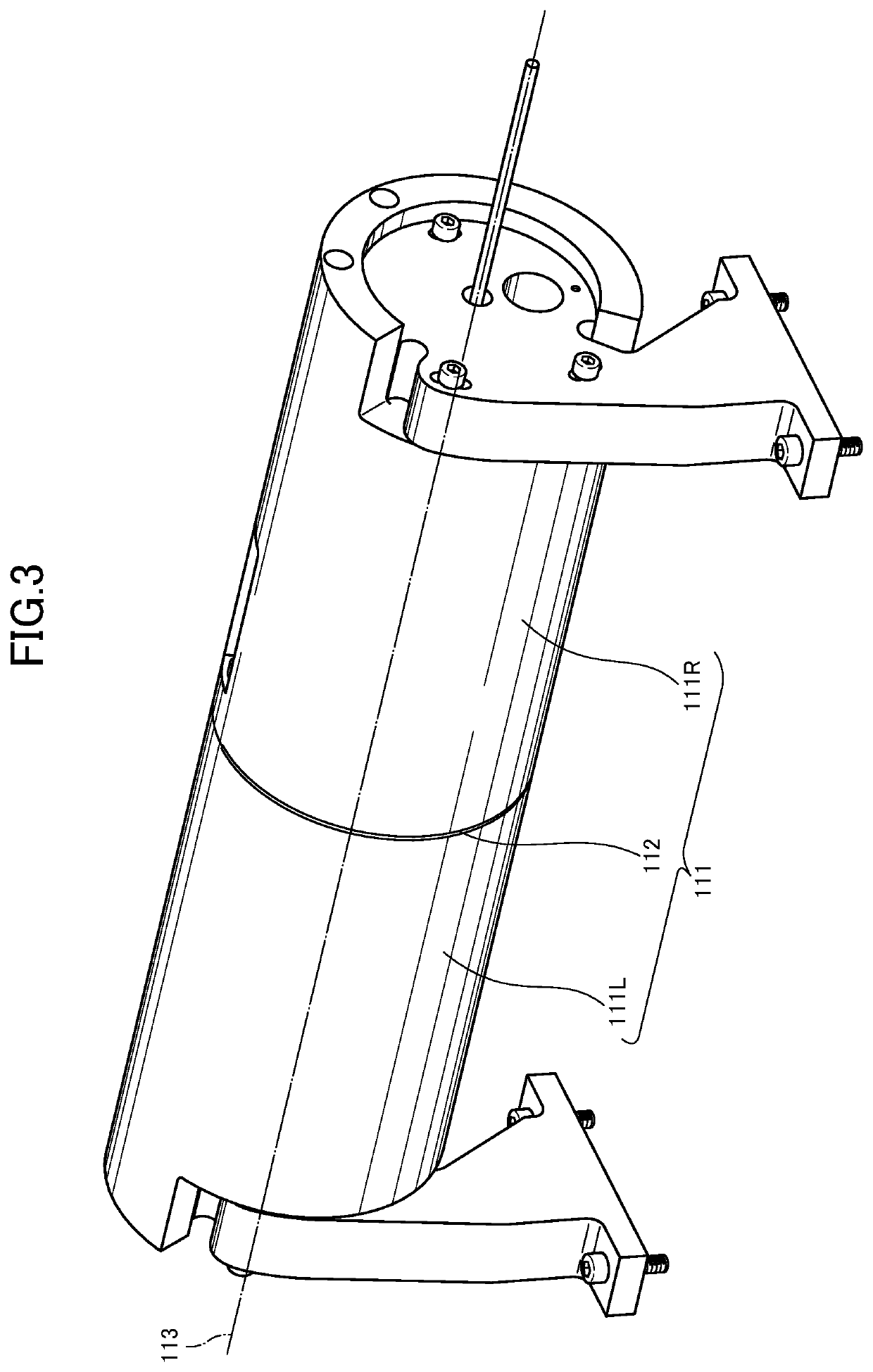
[0123]Here, FIG. 1 is a schematic diagram of a laser processing apparatus according to a first example of the present invention. FIG. 2 is a diagram illustrating a relationship between a cylindrical body and a thin plate according to the first example of the present invention. FIG. 3 is a diagram illustrating the appearance of the cylindrical body according to the first example of the present invention. FIG. 4 is a diagram illustrating a configuration of an opening of the cylindrical body according to the first example of the present invention. FIG. 5 is a diagram illustrating the arrangement of a reflecting members according to the first example of the present invention. And, FIG. 6 is a diagram illustrating a path and an irradiation angle of pulsed li...

example 2

[0151]Next, a laser processing apparatus according to the second example of the present invention will be described with reference to FIGS. 7 to 10, together with a laser processing method and a laser processed long thin plate material.

[0152]Here, FIG. 7 is a diagram illustrating a relationship between a cylindrical body and a thin plate according to a second example of the present invention. FIG. 8 is a diagram illustrating the appearance of the cylindrical body according to the second example of the present invention. FIG. 9 is a diagram illustrating a configuration of an opening of the cylindrical body according to the second example of the present invention. And FIG. 10 is a diagram illustrating another configuration of the opening of the cylindrical body according to the second example of the present invention.

[0153]The reference numerals of the 100s attached to the parts in the laser processing apparatus 100 of the first example described above are replaced with the reference ...


PUM

PropertyMeasurementUnit
Speedaaaaaaaaaa
Lightaaaaaaaaaa

Abstract

A laser processing apparatus and a laser processing method for improving the processing speed and forming uniform and highly accurate through holes when processing for forming fine through holes in a matrix in a long thin plate, and a thin plate having through holes in a matrix formed by such laser processing. A laser processing apparatus includes a cylindrical body having an opening on a circumferential surface around which a thin plate to be processed is wound obliquely, a thin plate transfer for transferring a thin plate wound around the cylindrical body in the longitudinal direction of the thin plate, a motor having a rotation axis arranged coaxially with a central axis of the cylindrical body, a reflecting member fixed to a rotating shaft of the motor, a laser light emitting means for emitting pulsed light. The apparatus continuously opens through holes in the thin plate.

Description

TECHNICAL FIELD[0001]The present invention relates to a laser processing apparatus and a laser processing method for forming fine through holes in a matrix on a long thin plate, and a laser processed long thin plate material. And in particular, the present invention relates to a laser processing technique, which is used in manufacturing a gas diffusion layer of a fuel cell, for a thin plate and a processed product using the same.BACKGROUND ART[0002]Conventionally, etching processing using chemical reactions have been widely used when processing a thin metal plate to form fine through holes therein.[0003]However, in forming through holes in a metal thin plate by etching processing, there has been big problems such as instability in shapes of through holes, large processing cost because of a large number of processes for wet processing, difficulty in forming through holes of 100 μm or less and difficulty in improving the processing speed.[0004]Further, in cases where a thin plate is n...

Claims


Application Information

Patent Timeline
IPC IPC(8): B23K26/382B23K26/08
CPCB23K26/0846B23K26/382B23K26/08B23K26/0838
Inventor YAMAKAWA, AKIOSOMA, NAOHIKOKANEKO, MITSUYUKI
Owner WIRED CO LTD
Why Eureka
Try Eureka