Projection display and method of displaying an overall picture

Active Publication Date: 2011-12-15
FRAUNHOFER GESELLSCHAFT ZUR FOERDERUNG DER ANGEWANDTEN FORSCHUNG EV
View PDF4 Cites 31 Cited by
  • Summary
  • Abstract
  • Description
  • Claims
  • Application Information

AI Technical Summary

Benefits of technology

[0014]In further embodiments of the present invention, the optical projection elements may be centered with regard to the associated subareas and may have a collimating effect.
[0015]In further embodiments of the present invention, a two-dimensional arrangement of field lenses associated with the op

Problems solved by technology

However, if one reduces the dimensions of the systems known in conventional technology in order to realize miniaturized picoprojectors, brightness losses of the projected picture will result, in particular.
Miniaturization of known projection systems is possible only to a limited extent due to the transmissible luminous flux being limited by

Method used


Image

  • Projection display and method of displaying an overall picture
  • Projection display and method of displaying an overall picture
  • Projection display and method of displaying an overall picture

Examples


Embodiment Construction

[0034]Before the present invention will be explained in more detail in the following with reference to the figures, it shall be noted that in the embodiments presented below, elements that are identical or identical in function are provided with identical reference numerals in the figures. Descriptions of elements bearing the same reference numerals are therefore mutually exchangeable and / or mutually applicable in the various embodiments.

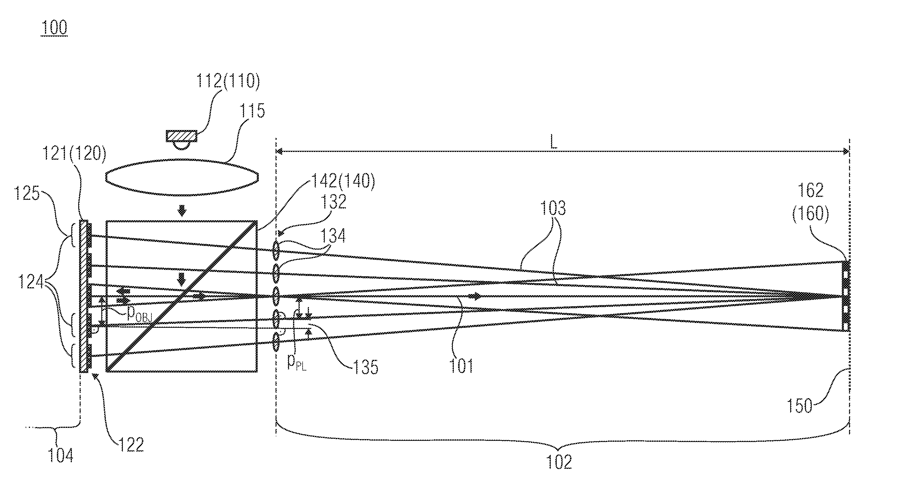
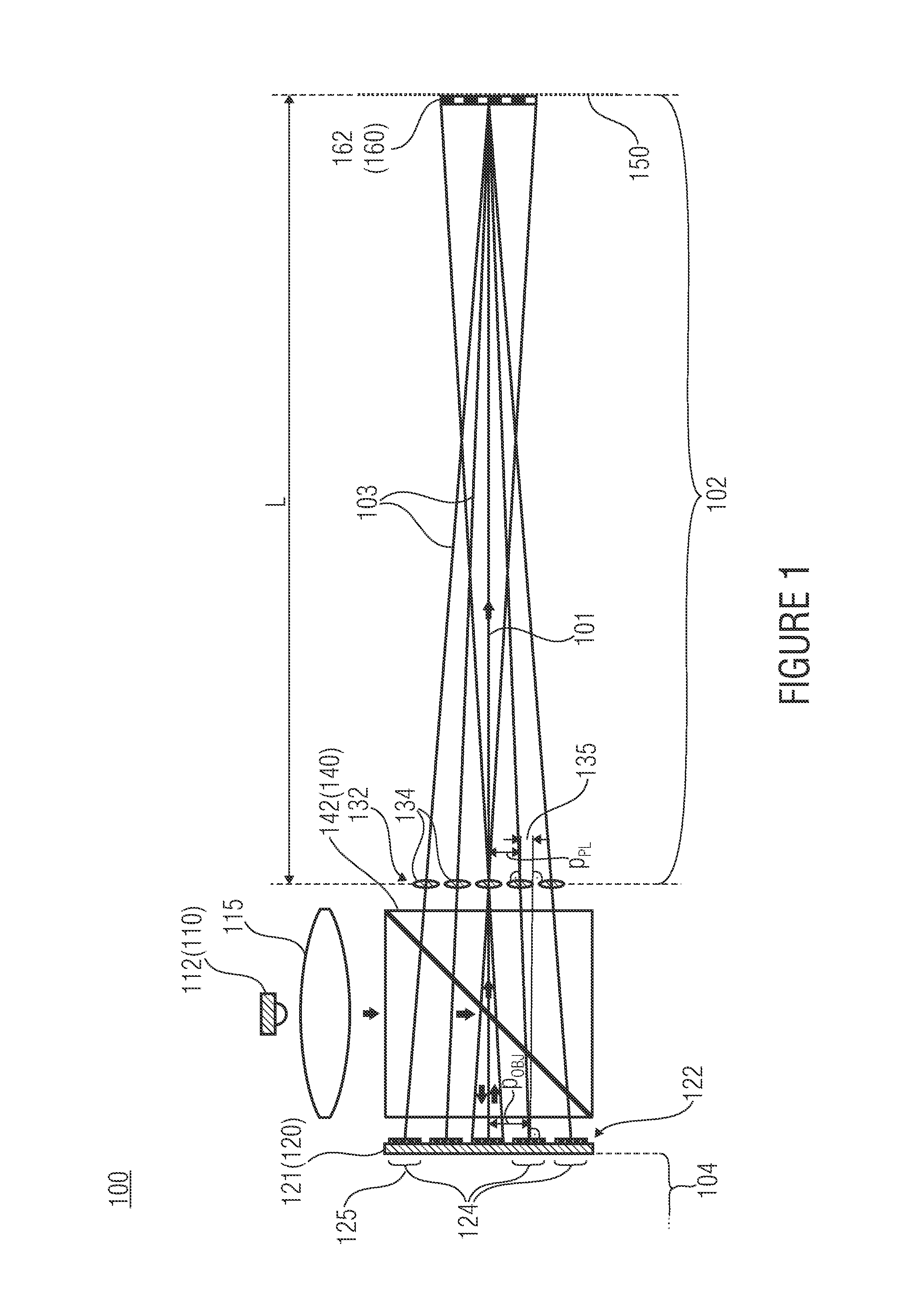
[0035]FIG. 1 shows a side view of a projection display 100 in accordance with an embodiment of the present invention. The projection display 100 shown in FIG. 1 comprises a light source 110, a reflective image generator 120, a two-dimensional arrangement 132 of optical projection elements 134 and a beam splitter 140. In this context, the reflective image generator 120 is configured to represent frames in a two-dimensional distribution 122 of its subareas 124. In addition, the two-dimensional arrangement 132 of optical projection elements 134 is conf...


PUM


Abstract

A projection display includes at least one light source, at least one reflective image generator configured to represent frames in a two-dimensional distribution of subareas of same, a projection optics arrangement having a two-dimensional arrangement of optical projection elements and being configured to image an associated subarea of the at least one image generator onto an image plane in each case, so that images of the frames superimpose within the image plane to form an overall picture, and at least one beam splitter arranged within an optical path between the at least one reflective image generator and the two-dimensional arrangement of optical projection elements, on the one hand, and the optical path between the at least one light source and the at least one reflective image generator, on the other hand.

Description

[0001]Embodiments of the invention relate to a projection display and to a method of displaying an overall picture. Further embodiments of the invention relate to a projection device based on a reflective liquid-crystal image generator and utilization of same.BACKGROUND OF THE INVENTION[0002]Projection of dynamic picture content onto a screen, or as a virtual picture, using a digital, reflective liquid-crystal-based image generator is based, in accordance with conventional technology, on projection devices having an imaging optical channel, or three channels, whose optical paths unite upstream from the optical projection element in order to realize the color mixture.[0003]In particular, US 2009 323 028 A1 shows picoprojectors that are LED-illuminated in a color-sequential manner. In addition, US 2009 237 616 A1 describes a projection display comprising three color channels combined upstream from the optical projection element.[0004]However, if one reduces the dimensions of the syste...

Claims


Application Information

Patent Timeline
IPC IPC(8): G03B21/14
CPCG02B2027/0123H04N9/3141G02B3/12G02B2027/0112G02B27/0101G02B2027/0185G02B2027/015G02B5/30G02B2027/0147G02B2027/011G03B21/00H04N5/74
Inventor SIELER, MARCELSCHREIBER, PETERFOERSTER, ERIK
Owner FRAUNHOFER GESELLSCHAFT ZUR FOERDERUNG DER ANGEWANDTEN FORSCHUNG EV
Why Eureka
Try Eureka