Induction streetlight

a technology of induction streetlights and housings, which is applied in the direction of fixed installation, lighting and heating equipment, lighting support devices, etc., can solve the problems of reducing the overall service life of the system, compromising system life and performance, and increasing the initial cost of heat sensitive components, so as to improve the service life and reduce the time required. , the effect of improving the cooling

Inactive Publication Date: 2011-12-15
U S ENERGY TECH INC
View PDF5 Cites 43 Cited by
  • Summary
  • Abstract
  • Description
  • Claims
  • Application Information

AI Technical Summary

Benefits of technology

[0007]The present invention streetlight improves upon the prior art by providing improved cooling for the newer technology induction lamps and by providing improvements in the lamp housing that reduce the time required to service the light. In its most basic form, the new streetlight comprises a main housing which includes separate, sealed, compartments for the induction lamp and the ballast or lamp electronics. Another separate compartment is provided for the photocell, the terminal block and the mast clamps. The lamp compartment of the housing features a multiplicity of heat sinks for conducting heat out of the compartment and into the housing where the heat is dissipated in the atmosphere through a combination of convection cooling and radiation. By providing separate lamp and ballast compartments, the ballast is better protected from the heat loading by the la

Problems solved by technology

Induction lamps do, however, have certain drawbacks, mainly higher initial cost and heat sensitive components which compromise system life and performance.
High temperatures affect both the electrical and lamp components typically located inside the streetlight, which in turn will reduce overall service life of the system.
Improved lamp life is an important aspect of streetlight design because streetlights are typically mounted at the top of tall light-poles, which makes servicing in the field difficult and costly.
The service of streetlights poses unusual dangers to workers because the lamps are typically located at substantial heights and therefore require special equipment to reach, and are typically situated in locations exposed to the hazards of vehicular traffic.
In addition, streetlights must often be serviced “live,” i.e. with the power on, be

Method used


Image

  • Induction streetlight
  • Induction streetlight
  • Induction streetlight

Examples


Embodiment Construction

[0019]The present invention will now be described more fully with reference to the accompanying drawings, in which preferred embodiments of the invention are shown. The invention may, however, may be embodied in many different forms and should not be construed as being limited to the embodiments set forth herein. Rather these embodiments are provided so that this disclosure will be thorough and complete, and will fully convey the scope of the invention to those skilled in the art. Like numbers refer to like elements throughout.

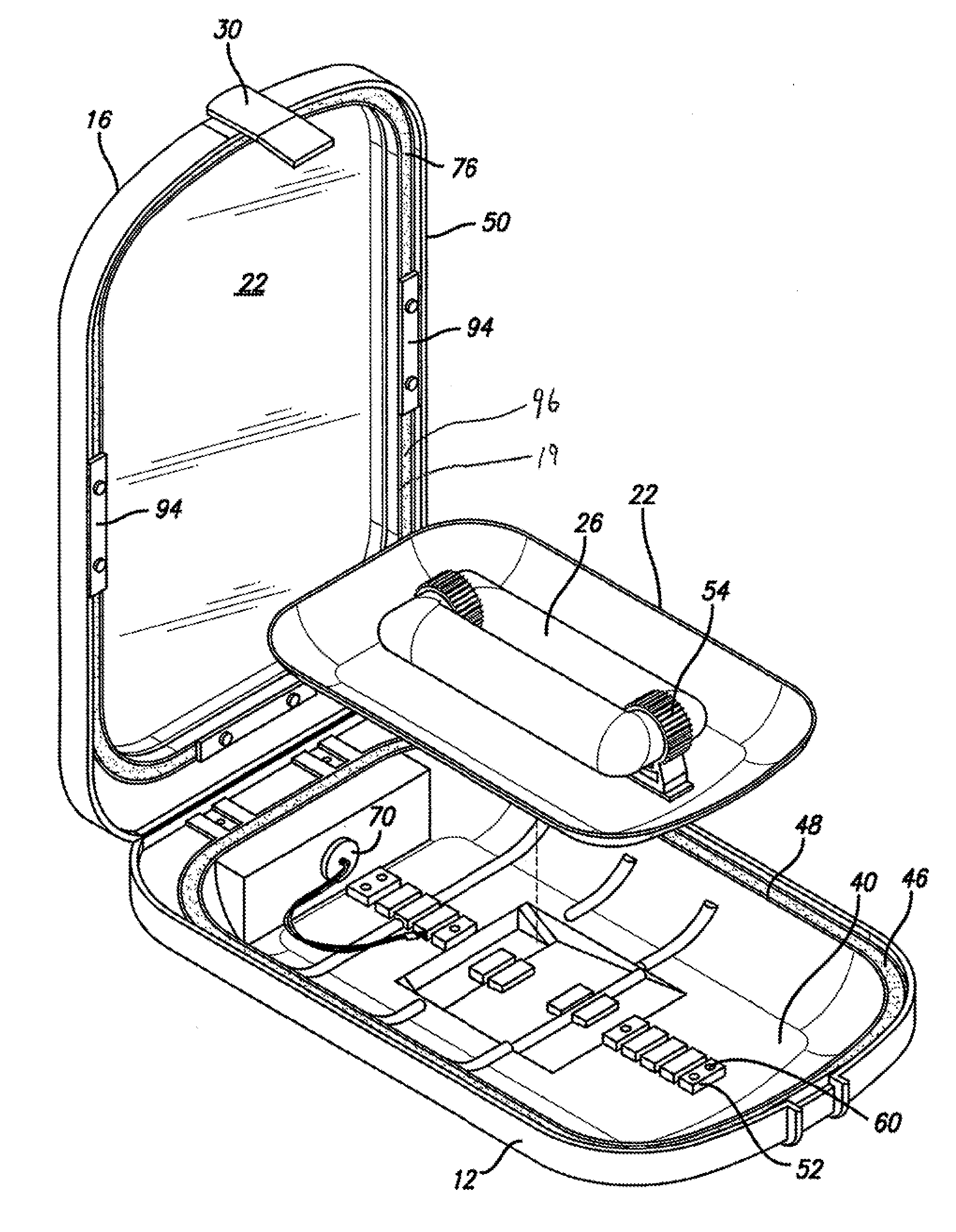
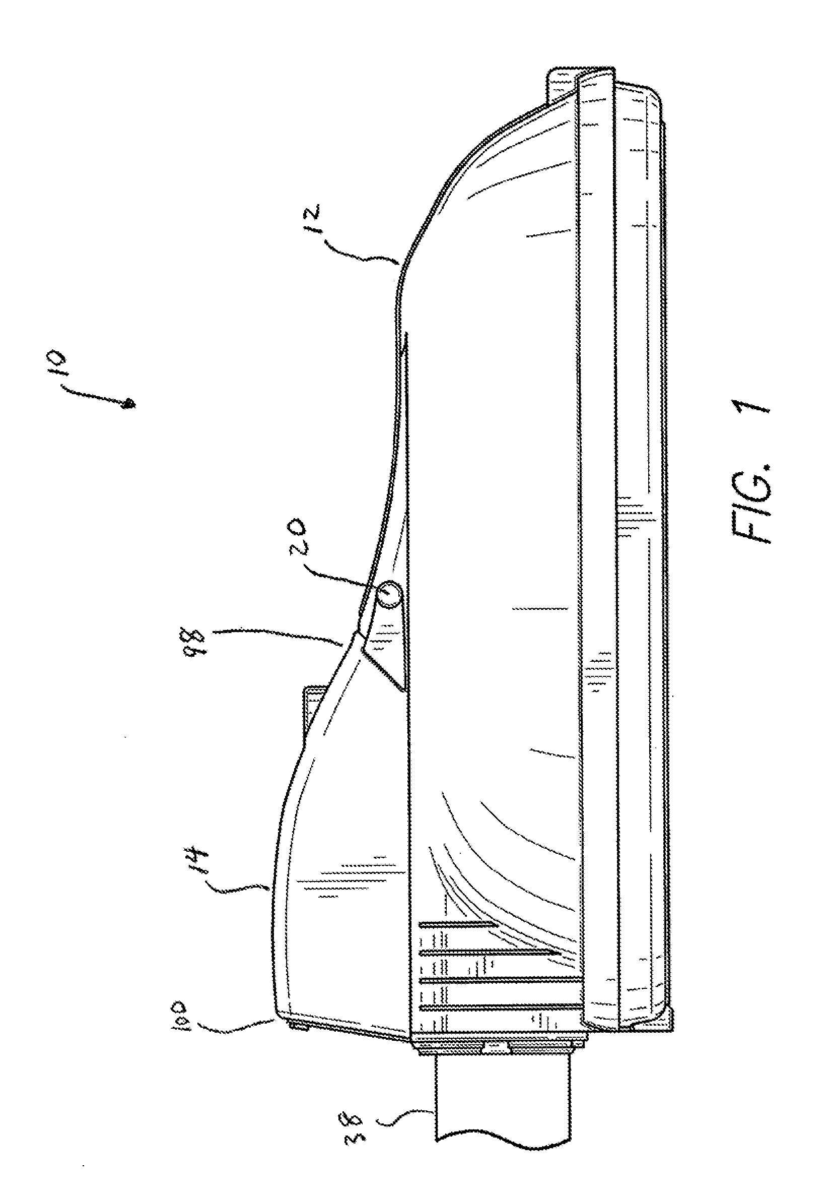
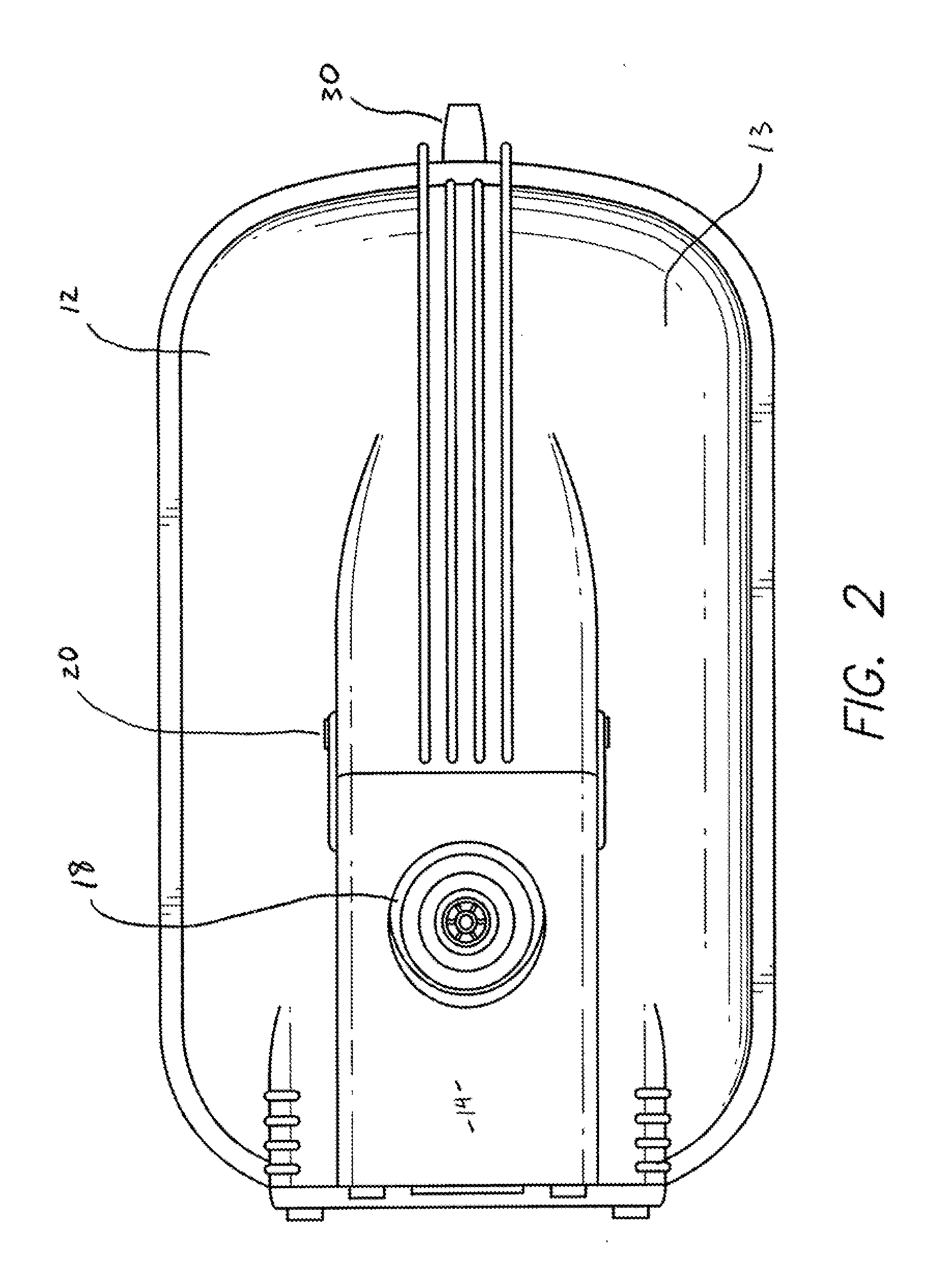
[0020]With reference to FIGS. 1 through 11, the present invention streetlight 10 includes a main housing 12 having an outer surface 13. The main housing 12 includes a lamp compartment 40 (see FIGS. 8-9), a ballast compartment 42 (see FIG. 6), and mast compartment 44 (see FIG. 7). Located within the lamp compartment 40 of the main housing 12 are a lamp 26 and a reflector 24 (see FIG. 8). Located within the ballast compartment is a ballast (lamp electronics) 32....


PUM


Abstract

An improved streetlamp featuring separate compartments for the lamp, ballast, photocell and wiring is provided. All electrical components of the streetlight are sealed from the elements and infestation from insects such as bees and wasps. All of the compartments may be readily opened without the use of tools and each electrical component and the light-glass can be readily removed and replaced with simple hand tools. Features for improved heat transfer to the atmosphere which results in a cooler running and longer lasting lamp are also provided.

Description

FIELD OF THE INVENTION[0001]The present invention relates generally to energy efficient streetlights and more particularly to an improved housing and assembly for an energy efficient streetlight wherein all major components of the lighting system may be readily removed from the housing for “in the field replacement” and wherein the housing features improved heat dissipation and isolation, among other improvements.BACKGROUND OF THE INFORMATION[0002]In recent years, there have been substantial improvements in streetlight technology. Previously, high intensity discharge (“HID”) streetlights typically used mercury-vapor, high pressure sodium or metal-halide lamp technologies. Recently, newer technology electrodeless induction, LED or plasma lamps have become to be used in streetlight applications. These lamps have several advantages over older HID systems which use magnetic ballasts. In particular, the newer energy efficient technologies last 5-10 times longer, experience significantly ...

Claims


Application Information

Patent Timeline
IPC IPC(8): F21V21/088F21V29/00F21V15/01
CPCF21V15/01F21V29/713F21V31/005F21V17/107F21V17/12F21V19/0075F21V19/009F21V21/116F21V23/009F21V23/023F21V23/0464F21Y2103/02F21S8/086F21W2131/103F21V29/505F21V29/507F21V29/004F21Y2103/30F21V29/74
Inventor HAM, RICHARD
Owner U S ENERGY TECH INC
Why Eureka
Try Eureka