Protective skin for robots

a technology for protecting skins and robots, applied in the direction of instrumentation, converting sensor output, program control, etc., can solve the problems of affecting the safety of robots, so as to reduce the consequences of an impact with the operator or the environment, reduce the cost of materials, and reduce the effect of production cos

Inactive Publication Date: 2011-12-15
COMMISSARIAT A LENERGIE ATOMIQUE ET AUX ENERGIES ALTERNATIVES
View PDF10 Cites 33 Cited by
  • Summary
  • Abstract
  • Description
  • Claims
  • Application Information

AI Technical Summary

Benefits of technology

The object of the invention is to provide a protection device for robots having the function, whatever the size of the protection device is, of reliably detecting the imminence of a collision between the body of a robot and the environment and determining its location in order to command the robot so that it avoids the impact.
Another advantage of the device of the invention is the low cost of the materials constituting it, its low production cost, and the possibility of industrial production.

Problems solved by technology

The consequences of a collision between the robot and its environment may therefore be disastrous, even at low speed: firstly there is the risk of damaging the environment, which may include fragile articles and human beings, and secondly the robot itself may be damaged in a collision with an element of the environment stronger than itself, for example a concrete wall.
The problem therefore arises of limiting the consequences of collisions that may occur if a robot of high inertia moves quickly in an environment that is not static.
Firstly, image processing is time-consuming, and that limits the speed at which the robot may move.
Secondly, the algorithms are complex and therefore they are of only moderate reliability.
Thirdly, those algorithms require considerable calculation resources.
Moreover, the field of view of a video camera may be accidentally obstructed, for example if the lighting is turned down or off completely, or else in the opposite situation of excessive lighting.
Video cameras are also complex pieces of equipment with a non-negligible risk of failure.
The difficulty of such a solution is to distinguish low environment / robot contact forces that are precursors of a collision from high forces that result from the inherent dynamics and mass of the robot, not to mention the inherent noise of the sensor.
Consequently, to obtain sufficient sensitivity it is necessary to filter the signals coming from the sensor, which is time-consuming and greatly increases the time needed to detect a collision.
However, when the robot is in motion, the inertia of a bumper and the stiffness of the pressure sensors make fine measurements uncertain, which may limit the sensitivity of the system when it is most needed at very beginning of the collision.
That kind of solution has the drawback that, when the robot is in motion, contact between the robot and the environment is detected too late to be able to prevent a collision.
A very short detection distance requires a large number of detectors, which is difficult to implement.
In contrast, if the number of sensors is low, the detection distance is relatively large, and so the sensors may accidentally detect parts of the robot other than that to which they are fixed.
However, such a sensor proves complex to install, in particular when covering a large area of the robot, notably because of the need to insert each electrode through the wall of the robot, the need to connect each electrode to the input of the multiplexer placed inside the robot by means of a wire, and the need to seal the deformable layer.
Covering a large area cannot be envisaged because of the difficulty of obtaining a deformable layer that is uniform over the whole of the sensor.

Method used


Image

  • Protective skin for robots
  • Protective skin for robots
  • Protective skin for robots

Examples


Embodiment Construction

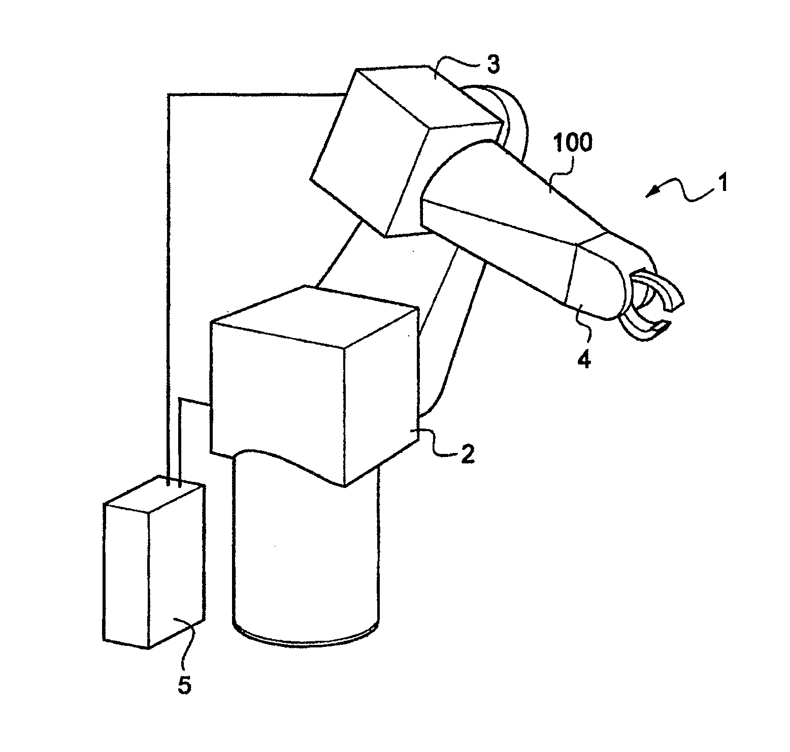
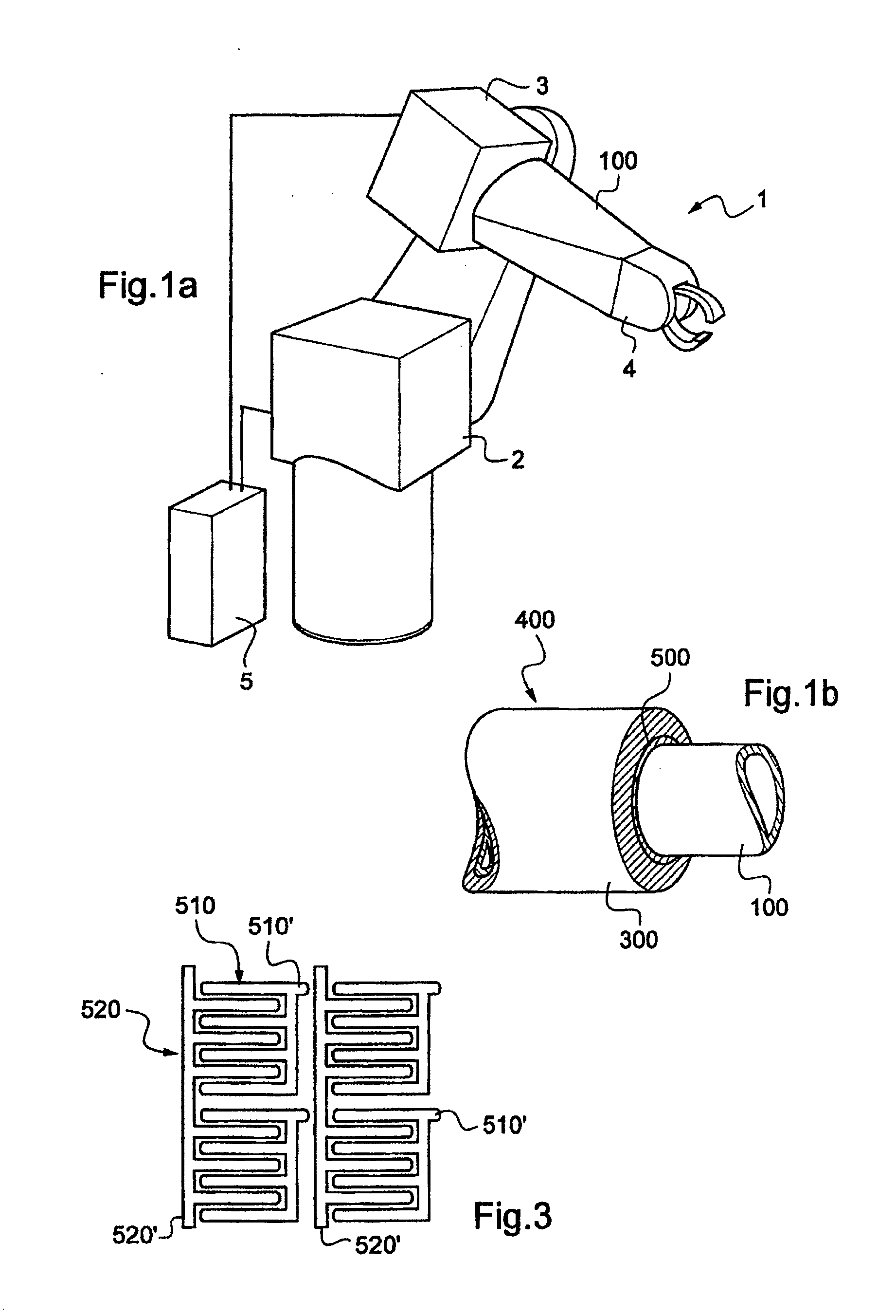
FIG. 1a is a perspective view of a standard robot 1 on which the detector device of the invention may be mounted.

The robot includes a motorized structure having motors 2, 3, and 4 connected to a control unit 5 executing a computer program controlling the motorized structure. Here the motorized structure includes a robot arm 100 having an exterior surface with at least a portion thereof covered by a detector device 400 of the invention that forms a skin on the robot arm.

The device 400 includes an electromechanical transducer 500 covering the exterior surface of the robot arm 100 and including a substrate 550 provided with electrodes 510, 520 and covered by a deformable layer 300.

The transducer is shown in detail in FIG. 2. The substrate 550 of the electromechanical transducer 500 includes a flexible base layer 551 on which the electrodes 510, 520 lie, a variable conduction layer 552 covering the base layer 551 and the electrodes 510, 520, a conductive layer 553 covering the variable ...


PUM

PropertyMeasurementUnit
speedaaaaaaaaaa
thicknessaaaaaaaaaa
timeaaaaaaaaaa

Abstract

Detector device arranged to cover at least one portion of a mobile appliance; the device has an electromechanical transducer including a substrate, a first series of electrodes, a second series of electrodes, and a deformable layer associated with the electrodes of the two series, the substrate, the electrodes, and the deformable layer forming a single unit mounted on the portion of the mobile appliance and arranged so that a current flowing between one of the electrodes of the first series and an adjacent electrode of the second series is proportional to a thickness of the deformable layer in register with the electrodes. The substrate including a base layer to which are attached the electrodes of the first series and the electrodes of the second series, which have facing portions, and a variable conduction layer that covers the base layer and the electrodes.

Description

The invention relates to a detector device adapted to cover at least part of a mobile appliance such as a robot or any other type of mobile machine and more particularly a mobile machine near which personnel are liable to be working. To be more precise, the application of this device is to detecting a collision in advance in order to take measures to reduce or eliminate the negative effects of that collision.BACKGROUND OF THE INVENTIONIndustrial robots are usually constructed with an architecture that is heavy and rigid. The consequences of a collision between the robot and its environment may therefore be disastrous, even at low speed: firstly there is the risk of damaging the environment, which may include fragile articles and human beings, and secondly the robot itself may be damaged in a collision with an element of the environment stronger than itself, for example a concrete wall. The problem therefore arises of limiting the consequences of collisions that may occur if a robot ...

Claims


Application Information

Patent Timeline
Patent Type & Authority Applications(United States)
IPC IPC(8): G05B19/04G01L1/18
CPCG01D5/16G01L1/205G01L1/18G01D5/2417B25J13/084B25J19/0091B25J19/063
Inventor COLLEDANI, FREDERICLAMY, XAVIER
Owner COMMISSARIAT A LENERGIE ATOMIQUE ET AUX ENERGIES ALTERNATIVES
Why Eureka
Try Eureka