Method for creating speed profiles for digital maps

a technology of speed profile and digital map, applied in the field of digital maps, can solve the problems of inaccurate speed limit information, inability to provide any indication of the most efficient speed at which to drive any particular road segment, etc., and achieve the effect of reducing the energy consumption of vehicles driven with frequent start-stop motion and aggressive acceleration-deceleration

Active Publication Date: 2011-12-15
TOMTOM GLOBAL CONTENT
View PDF19 Cites 65 Cited by
  • Summary
  • Abstract
  • Description
  • Claims
  • Application Information

AI Technical Summary

Benefits of technology

[0012]The invention provides a method for creating longitudinally distributed speed data useful for various traffic modeling applications based on free flow traffic conditions. An optimal time span is identified with free flow traffic conditions along a road segment, e.g. early morning with good light conditions. Probe data recorded during the optimal time span and selected on basis of e.g. lane or vehicle type, is collected and then used to statistically derive a longitudinally distributed speeds at positions along the road segment during the optimal time span. Alternatively, probe data representative of the fastest probes for a road segment and direction may be selected and collected without identifying a specific optimal time span. The longitudinally distributed speeds are then associated with the road segment and either stored in a stand-alone database or added to an existing digital map as a data layer. The longitudinally distributed speeds represent realistic free flow driving conditions against which the instantaneous driving speed of any vehicle can be compared for various traffic modeling applications.
[0013]In one embodiment of this invention, the instantaneous driving speed of a vehicle is compared to the longitudinally distributed speed for that position so that real-time energy efficient driving instructions can be issued. In another embodiment of this invention, instantaneous driving speed of one or more vehicles is compared to the longitudinally distributed speeds for the purpose of assessing the flow efficiency of traffic along a road segment.
[0014]According to another aspect of this invention, a method for making road traffic flow efficiency estimates based on free flow conditions derived from select probe data is described. A digital map is provided having at least one longitudinally extending road segment. Probe data is collected from a plurality of probes traversing the road segment, each probe developing a respective probe trace comprising a sequence of discrete probe positions recorded at a particular time of day. An optimal time span is identified with free flow traffic conditions. Probe data recorded during the optimal time span is selected and then used to statistically derive longitudinally distributed speeds at positions along the road segment during the optimal time span. Alternatively, probe data representative of the fastest probes for a road segment and direction may be selected and collected without identifying a specific o

Problems solved by technology

Traditional routing methods use maximum speed limits as exist along road segments to calculate travel time estimates, however in practice speed limit information is not accurate because these speeds are not always possible at various times of the day.
While very useful, these prior art speed profile techniques do not provide any indication of the most efficient speed at which to drive any particular road segment, or indeed any indication of the actual manner (e.g., acceleration/deceleration rates) in which a vehicle traverses a particular road segment.
It is known, for

Method used


Image

  • Method for creating speed profiles for digital maps
  • Method for creating speed profiles for digital maps
  • Method for creating speed profiles for digital maps

Examples


Embodiment Construction

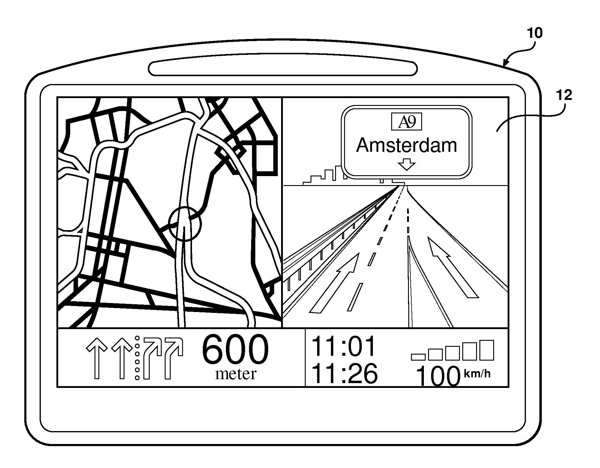
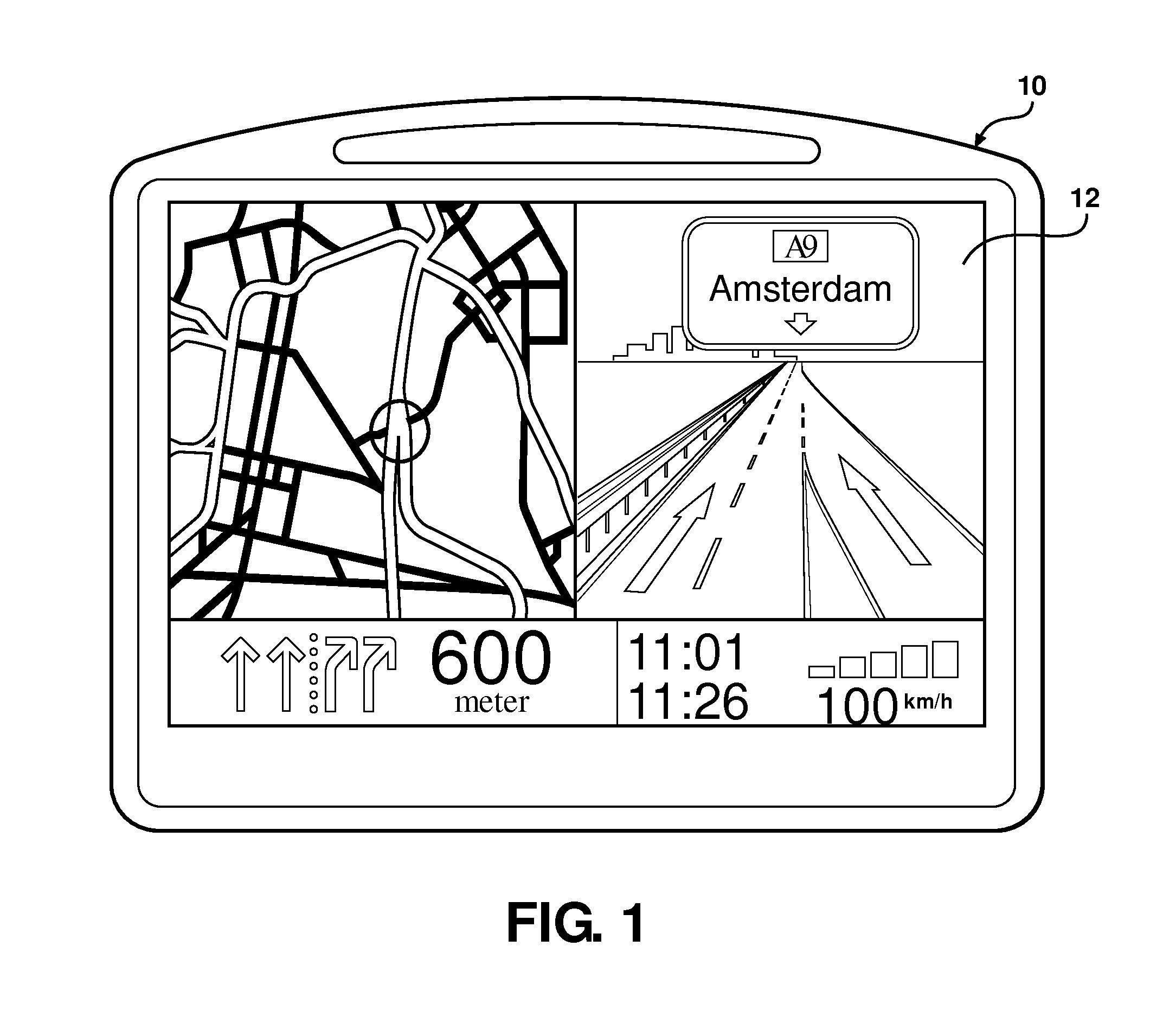
[0029]Referring to the Figures, wherein like numerals indicate like or corresponding parts throughout the several views, this invention pertains to position reading devices, navigation systems, ADAS systems with GNSS (Global Navigation Satellite System), and the digital maps used by navigation systems. This invention is therefore applicable to all kinds of navigation systems, position reading devices and GNSS enabled units including, but not limited to, handheld devices, PDAs, mobile telephones with navigation software, and in-car navigation systems operating as removable or built-in devices. The invention can be implemented in any type of standard navigation system available on the market, on mapping and navigation web sites / servers as far as energy efficient route planning is concerned, as well as suitable systems which may be developed in the future.

[0030]The navigation-capable device typically includes a computer readable medium having navigation software recorded thereon. A mic...


PUM


Abstract

Probe data collected at times of low traffic density is analyzed to derive a Raw Road Design Speed Limit (RRDSL, 16) for each road segment or group of segments in a digital map. The RRDSL (16), comprised of longitudinally distributed Pt speeds, is associated with the road segment and stored in a digital medium to indicate the limits of the road section in free flow traffic. The longitudinally distributed speeds may be limited by local speed limits or other business logic to establish a Legal Raw Road Design Speed Limit (LRRDSL, 17). Either the RRDSL (16) or the LRRDSL (17) can be further modified to smooth acceleration and deceleration rates between changes in the longitudinally distributed speeds to create an Optimal Longitudinal Speed Profile (OLSP, 18), which represents optimized energy consumption. A signal can be produced if a driver's current speed rises unacceptably above a longitudinally distributed speed in real time. The signal can be audible, visible and/or haptic. Real-time traffic density information can be inferred by comparing current speed data to the longitudinally distributed speed for that position. If the current speed is consistently lower than the longitudinally distributed speed for that position, an inference is drawn that the road section is inefficient. Road efficiency assessments can be transmitted to a service center and/or other vehicles, and used by navigation software.

Description

STATEMENT OF COPYRIGHTED MATERIAL[0001]A portion of the disclosure of this patent document contains material which is subject to copyright protection. The copyright owner has no objection to the facsimile reproduction by anyone of the patent document or the patent disclosure, as it appears in the PTO patent file or records, but otherwise reserves all copyright rights whatsoever.BACKGROUND OF THE INVENTION[0002]1. Field of the Invention[0003]This invention relates to digital maps of the type for displaying road or pathway information, and more specifically toward a method for supplementing a digital map with longitudinal speed profile information and toward a navigation device or any GNSS enabled unit used in conjunction therewith.[0004]2. Related Art[0005]Personal navigation devices like that shown generally at 10 in FIG. 1, for example, utilize digital maps combined with accurate positioning data from GPS or other data streams. These devices 10 have been developed for commuters see...

Claims


Application Information

Patent Timeline
IPC IPC(8): G08G1/00G01C21/26
CPCG01C21/32Y02B60/42G01C21/3469Y02D30/00G01C21/3492
Inventor HIESTERMANN, VOLKERVAN ESSEN, ROBERT JOANNESBASTIAENSEN, EDWINT'SIOBBEL, STEPHEN
Owner TOMTOM GLOBAL CONTENT
Why Eureka
Try Eureka