Improvements to work attachment assemblies

a technology for working attachments and assemblies, applied in the direction of basic electric elements, couplings, constructions, etc., can solve the problems of wear and tear, mounting the retention member to the body, and the assembly disclosed by the jr sales patent has a number of limitations, so as to facilitate the engagement of the sets of connectors, the effect of withstanding knocks

Inactive Publication Date: 2011-12-22
DOHERTY ENGINEERED ATTACHMENTS
View PDF8 Cites 13 Cited by
  • Summary
  • Abstract
  • Description
  • Claims
  • Application Information

AI Technical Summary

Benefits of technology

[0073]In a preferred embodiment the connectors are Quick Release Connectors (QRCs) as known to those skilled in the art. In this embodiment the QRCs are complementary male and female connector halves. The female connector has a spring biased latch to secure the male and female halves relative to each other. Movement of the latch relative to the female connector causes engaged pairs of connectors to release each other. In some embodiments the connector halves include a spring release mechanism to force the connector halves apart when the latch is released. In a preferred embodiment, the housings include impact absorbers. In this embodiment, the mountings may be mounted on compressible supports. These compressible supports may be formed from rubber or ...

Problems solved by technology

However, this involves the operator getting out of the excavator and getting close to the work attachment.
However, the assembly disclosed by the JR Sales patent has a number of limitations.
One of these disadvantages is the mounting of the retention member to the body.
Over time the pressure exerted on the retention member by the moveable jaw causes wear and tear.
The retention member may therefore be prone to failure.
Should the actuator or moveable jaw fail with the coupler in an inverted position, the effectiveness of the retention member is compromised and this could pose a safety risk.
A further disadvantage of the JR Sales patent is that the pin is not...

Method used


Image

  • Improvements to work attachment assemblies
  • Improvements to work attachment assemblies
  • Improvements to work attachment assemblies

Examples


Embodiment Construction

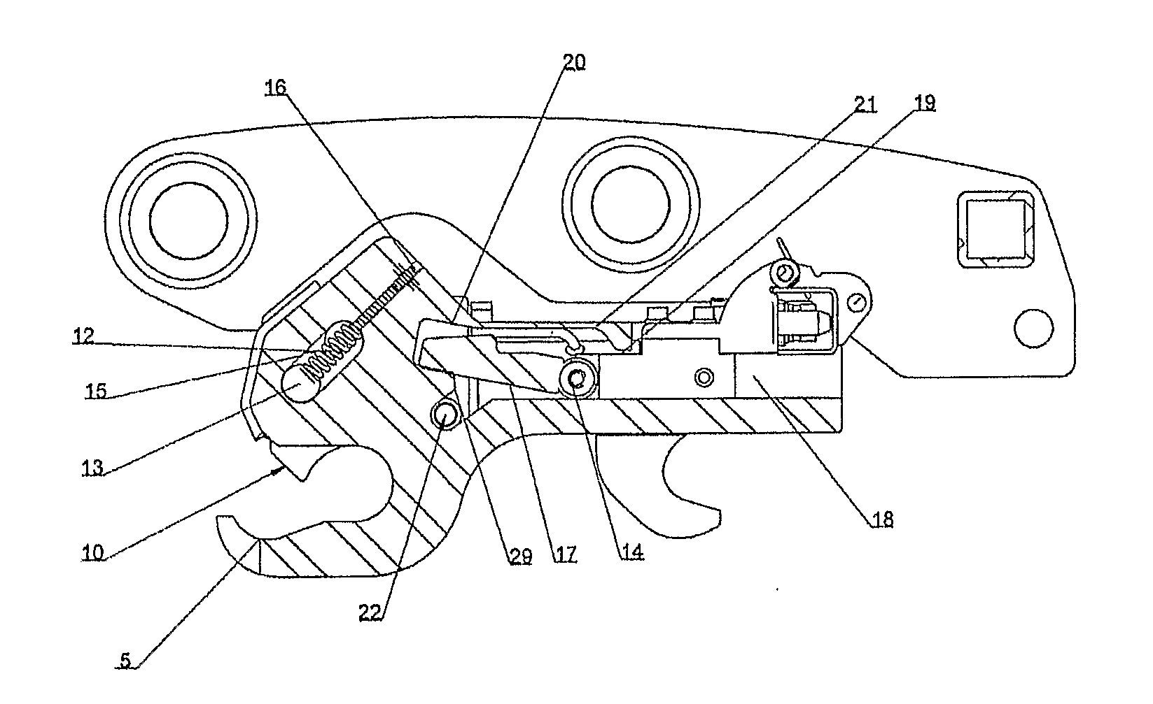
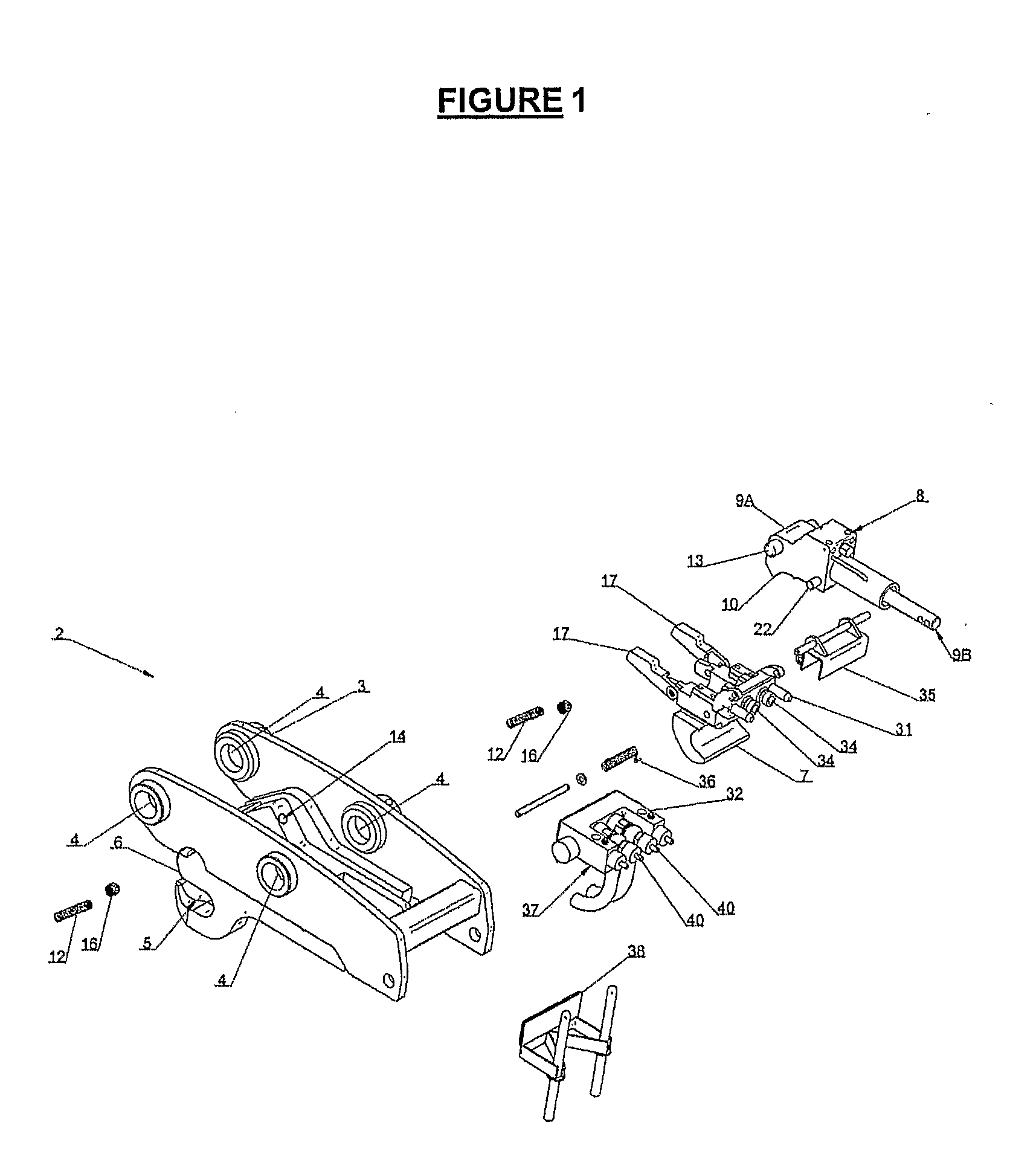
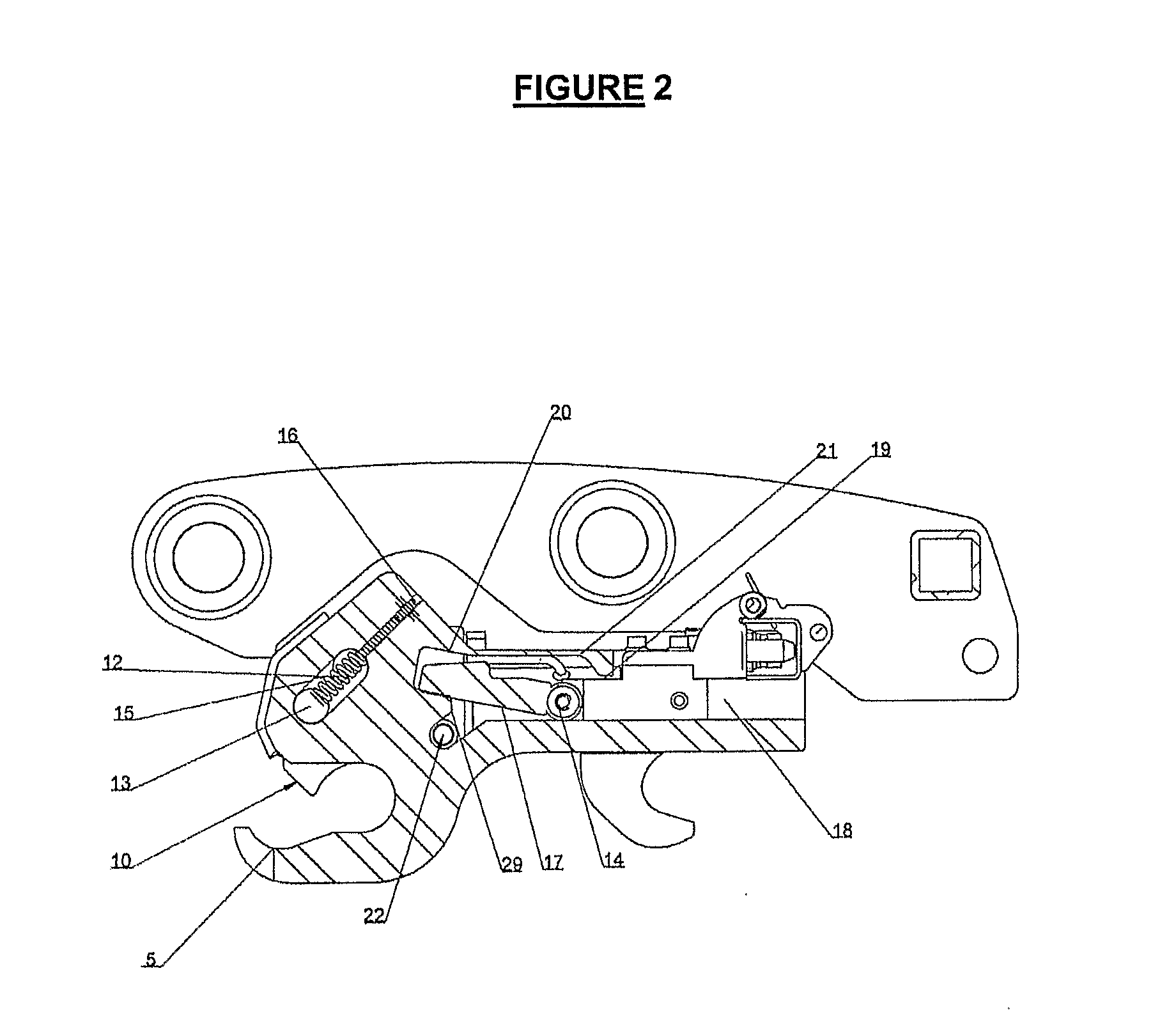
[0088]The present invention relates to improvements to work attachment assemblies (1) for use with excavators (not shown in the drawings). Like numbers refer to like components throughout the Figures.

[0089]Referring to FIG. 1 which is an exploded view showing the components of the work attachment assemblies, and FIG. 2 showing a side cross-sectional view of a coupler (2). The components of the coupler (2) will be discussed in the order in which they are assembled.

[0090]The coupler (2) has a body (3) to house its components. The body (3) facilitates attachment of the coupler (2) to an excavator arm (not shown). The attachment is via apertures (4) through which fasteners (not shown) can extend. This is as should be known to those skilled in the art. The body (3) has a first jaw (5) formed integrally at one end (6). A hydraulic cylinder (8) is positioned within the body (3). A second jaw (7) is secured to the hydraulic cylinder (8) at its first end (9A). The hydraulic cylinder (8) is c...


PUM

PropertyMeasurementUnit
Forceaaaaaaaaaa
Contraction enthalpyaaaaaaaaaa

Abstract

A method of releasing a work attachment from a coupler (2), wherein the work attachment is secured to the coupler via two pins held within two jaws (5, 7), the method including the steps of: (a) moving a jaw (7) to release a first pin (b) changing the orientation of the coupler (2) and work attachment relative to each other (c) moving the jaw (7) in the opposite direction to that in step (a); characterised by the step of: (d) moving the jaw (7) in the opposite direction to that in step (c) characterised in that the action of step (c) moves a safety link (17) to a release position, thereby allowing a locking portion (10) to release a second pin from a jaw in step (d).

Description

CROSS REFERENCES[0001]This application is a United States National Stage Application claiming priority under 35 U.S.C. 371 from International Patent Application No. PCT / NZ2009 / 000236 filed on Nov. 3, 2009, which claims the benefit of priority from New Zealand Patent Application No. 572477, filed on Nov. 3, 2008, the entire contents of which are herein incorporated by reference.FIELD OF THE INVENTION[0002]The present invention relates to improvements to work attachment assemblies and in particular work attachment assemblies for use with work machines such as excavators.BACKGROUND OF THE INVENTION[0003]Work machines such as excavators use a variety of work attachments. These attachments include buckets, graders, grapples or drilling attachments. It is desirable to have a releasable attachment between the construction vehicle and the work attachment to easily and rapidly change the work attachment. Generally a releasable attachment is provided by two or more jaws which engage pins on t...

Claims


Application Information

Patent Timeline
IPC IPC(8): E02F9/24B23P11/00
CPCE02F3/3618E02F3/3622E02F3/3645Y10T403/24E02F3/3654E02F3/3677Y10T29/49815E02F3/365
Inventor DOHERTY, JEREMY GLENDOHERTY, PAUL JAMES
Owner DOHERTY ENGINEERED ATTACHMENTS
Why Eureka
Try Eureka