Fuel efficient powertrain cooling systems and radiator modules

a technology of powertrain cooling system and radiator module, which is applied in the direction of indirect heat exchangers, machines/engines, light and heating apparatus, etc., can solve the problems of significant aerodynamic drag on the vehicle, limited powertrain cooling system, and corresponding reduction in fuel economy, so as to achieve less cooling efficiency

Active Publication Date: 2011-12-22
GM GLOBAL TECH OPERATIONS LLC
View PDF12 Cites 52 Cited by
  • Summary
  • Abstract
  • Description
  • Claims
  • Application Information

AI Technical Summary

Problems solved by technology

However, the intake of such a large volume of airflow through the vehicle grill results in the exertion of significant aerodynamic drag on the vehicle and a corresponding reduction in fuel economy.
However, such powertrain cooling systems are still limited in certain respects and generally fail to provide optimal heat rejection-to-fuel consumption ratios over a wide range of operating conditions.

Method used


Image

  • Fuel efficient powertrain cooling systems and radiator modules
  • Fuel efficient powertrain cooling systems and radiator modules
  • Fuel efficient powertrain cooling systems and radiator modules

Examples


Embodiment Construction

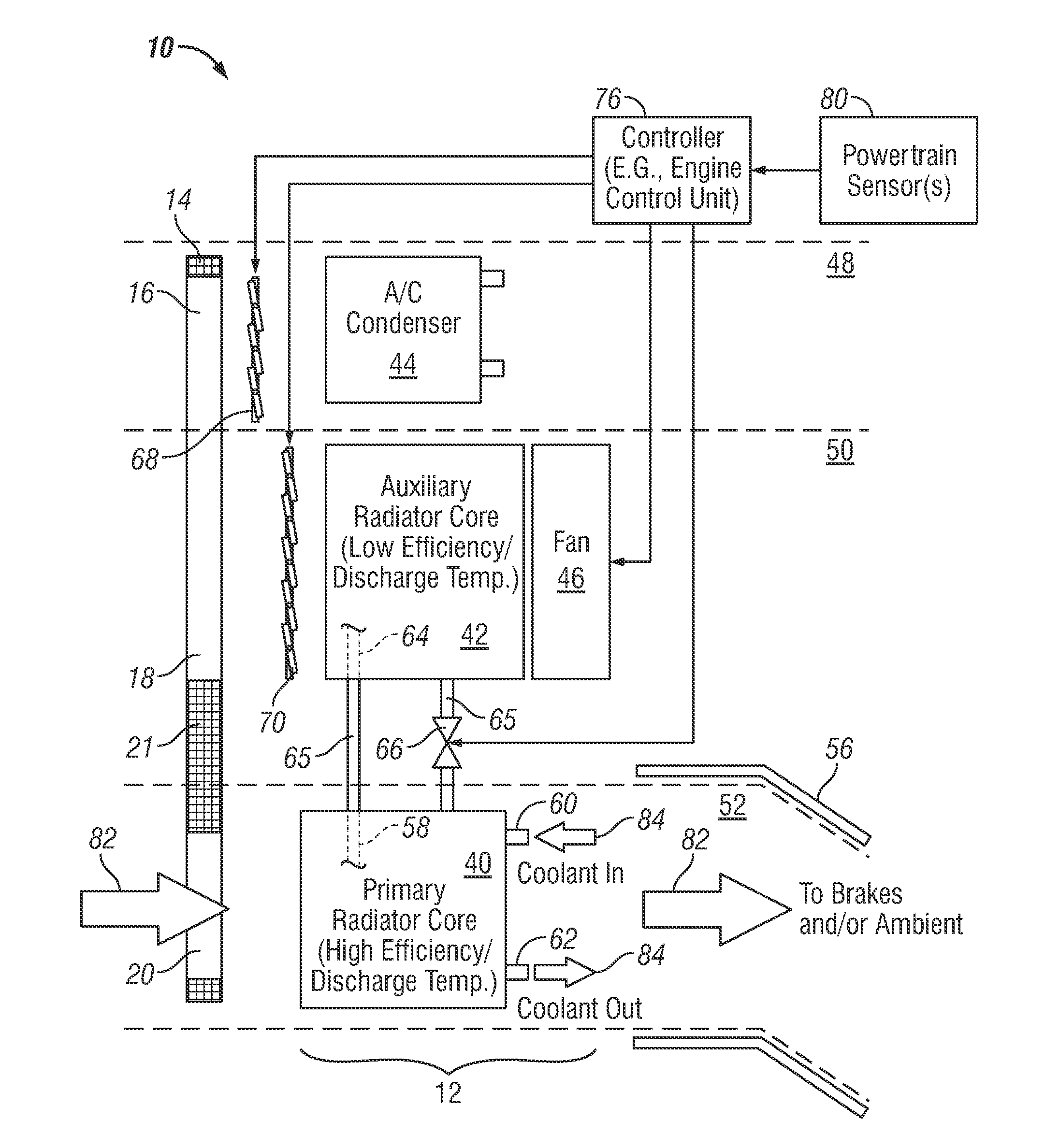
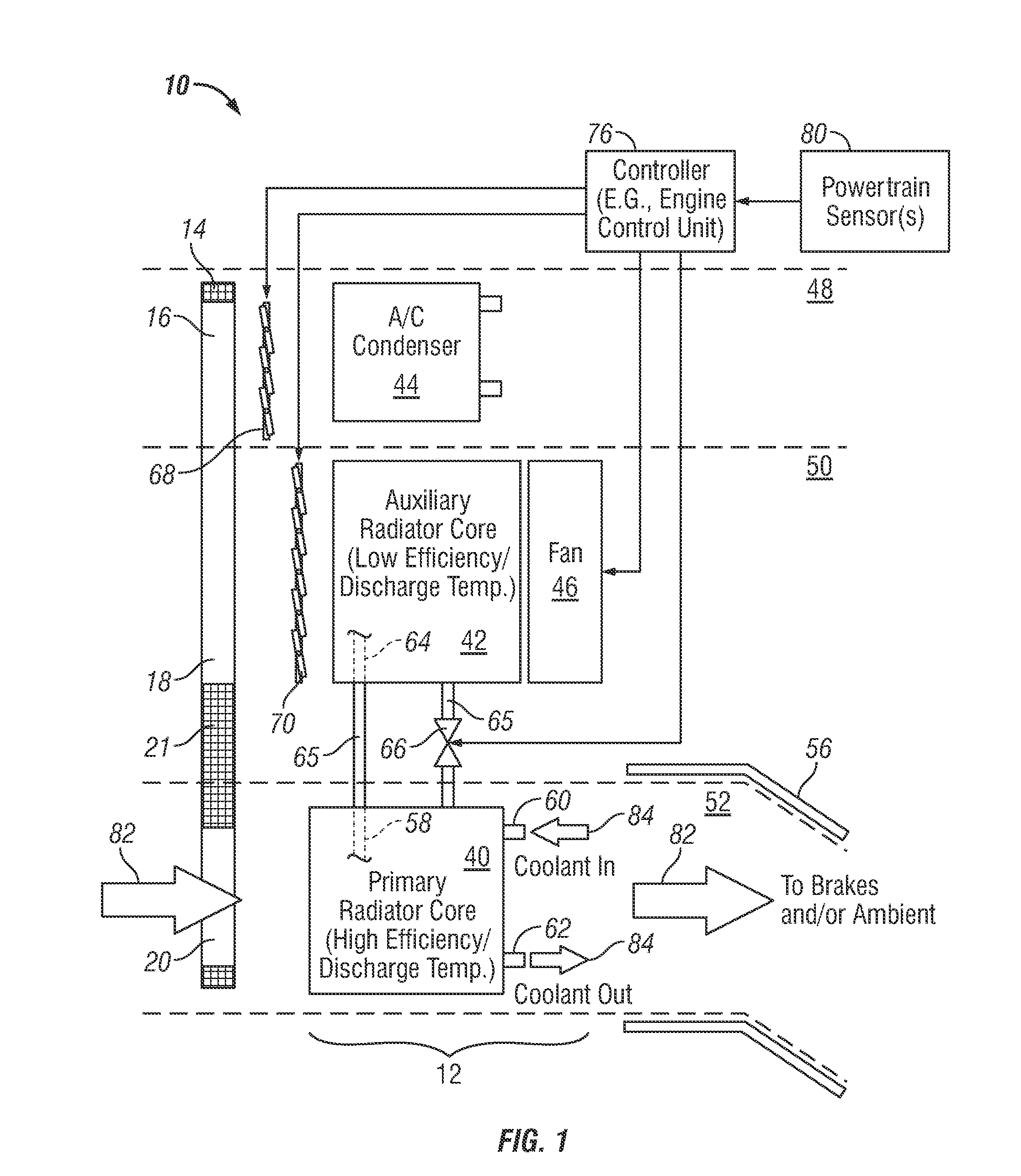
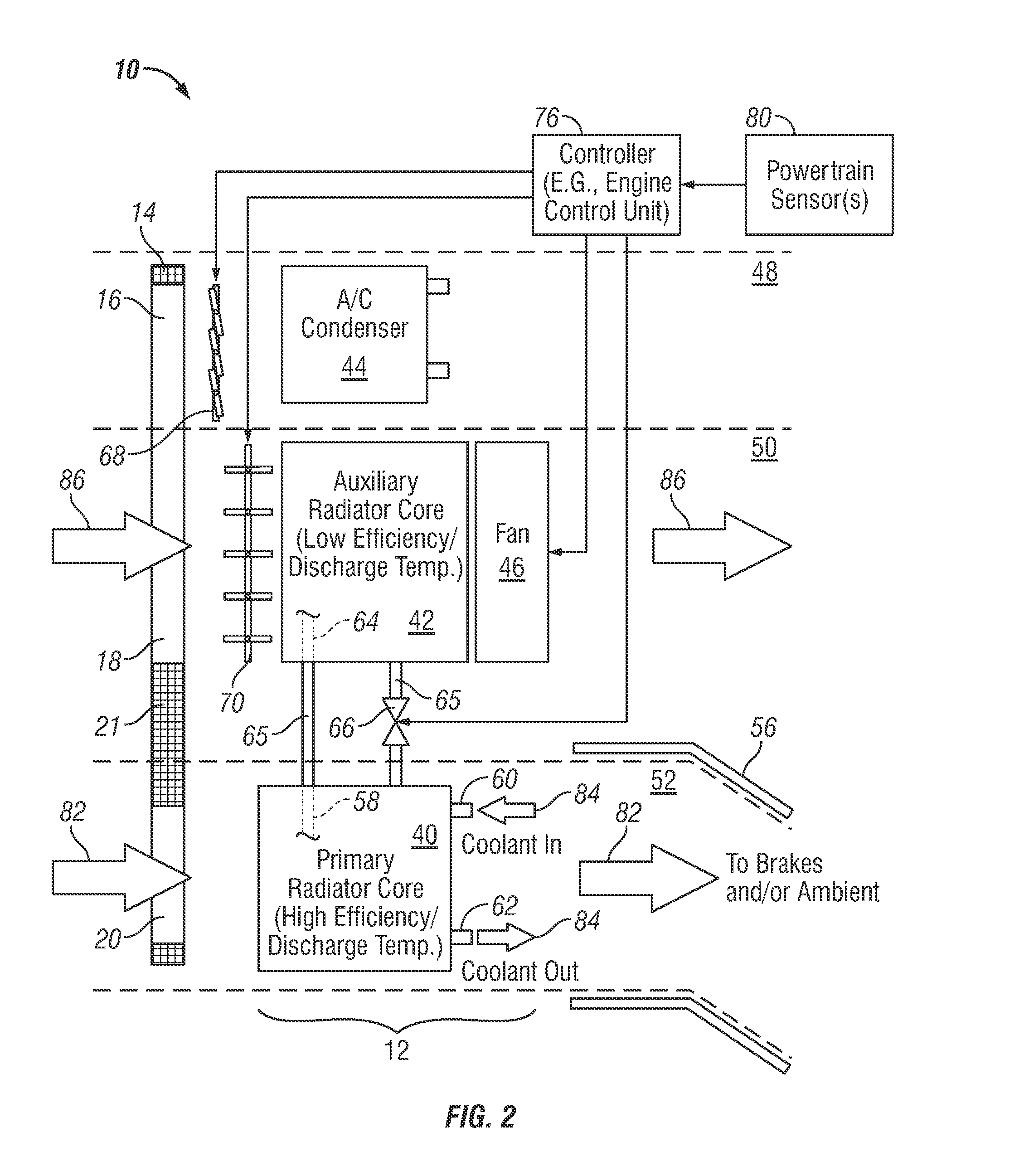
[0012]The following Detailed Description is merely exemplary in nature and is not intended to limit the invention or the application and uses of the invention. Furthermore, there is no intention to be bound by any theory presented in the preceding Background or the following Detailed Description.

[0013]FIGS. 1, 2, and 3 are functional diagrams of a vehicular powertrain cooling system 10 including a fuel efficient radiator module 12 in accordance with an exemplary embodiment of the present invention. As will be explained more fully below, powertrain cooling system 10 is operable in at least two modes: (i) a fuel efficient cooling mode suitable for normal or “everyday” usage, and (ii) an increased capacity cooling mode suitable for usage under “extreme use” conditions requiring dissipation of relatively high heat loads. In many embodiments, powertrain cooling system 10 will be operable in a fuel efficient cooling mode and a number of increased capacity cooling modes. In the illustrated...


PUM


Abstract

Embodiments of a powertrain cooling system and embodiments of a radiator module are provided for deployment onboard a vehicle. In one embodiment, the powertrain cooling system includes a first airflow path, a second airflow path, a primary radiator core positioned in the first airflow path, an auxiliary radiator core position in the second airflow path, and a first airflow valve positioned in the second airflow path upstream of the auxiliary radiator core. The first airflow valve is movable between a closed position wherein the first airflow valve impedes airflow to the auxiliary radiator core and an open position.

Description

TECHNICAL FIELD[0001]The following disclosure relates generally to vehicular cooling systems and, more particularly, to embodiments of a fuel efficient powertrain cooling system and radiator module.BACKGROUND[0002]Most modern vehicles are equipped with a liquid cooling system (referred to herein as a “powertrain cooling system”) that continually circulates a coolant fluid (e.g., antifreeze) to dissipate excess heat generated by the vehicle's internal combustion engine and to provide other heat-transfer functions (e.g., heating of other engine fluids; rapid warming of the engine upon start-up; warming of a heater core included within the vehicle's heating, ventilation, and air conditioning system; etc.). A conventional powertrain cooling system typically includes, amongst other components, a radiator core having a plurality of cooling fins interspersed with a plurality of metal tubes to form a generally rectangular unit, which is mounted between the vehicle's grill and engine compart...

Claims


Application Information

Patent Timeline
Patent Type & Authority Applications(United States)
IPC IPC(8): F01P1/00F28D1/00
CPCB60H1/3227B60H1/3229F01P7/165B60K11/085F01P7/12B60K11/04Y02T10/88
Inventor CHARNESKY, SCOTT P.FADLER, GREGORY J.LOCKWOOD, THOMAS K.GOLSCH, KEVIN A.
Owner GM GLOBAL TECH OPERATIONS LLC
Why Eureka
Try Eureka