Pipeline instrumentation and control system

a technology of instrumentation and control system and pipeline, which is applied in the direction of transmission, fluid removal, survey, etc., can solve the problems of system interference, high requirement for providing such information, and difficult task of extraction of hydrocarbons from well system, and achieve the effect of efficient communication link

Inactive Publication Date: 2011-12-22
WFS TECH
View PDF13 Cites 8 Cited by
  • Summary
  • Abstract
  • Description
  • Claims
  • Application Information

AI Technical Summary

Benefits of technology

[0008]It is an object of the present invention to provide a radiating cable system for the transfer of signals, for example data signals, in a hostile environment such as a well system in which signals are transferred in a simple manner.

Problems solved by technology

The extraction of hydrocarbons from a well system is a very challenging task with such systems typically comprising a complex network of metallic pipes through which oil or gas is supplied from an underground reservoir to a production platform.
The requirement to provide such information is extremely challenging due to the very constrained nature of the pipe structure.
However, these systems suffer from interference from the acoustic noise generated by drilling operations.
Acoustic signaling within the pipe walls and through the fluid carried by production pipes suffers from similar limitations.
This technique has also been found to be unreliable in an extreme environment such as in a well system.
Furthermore, the production tubing and casing are assembled in sections and this complicates deployment of a wired system which has to be threaded through the centre of the pipe as each section is deployed.
In this environment electrically conductive cables and electrically conductive connectors provide very low reliability.
Moreover, hard wired cables are permanently interfaced to control devices and sensors and should one part of the system fail then this often results in failure of the whole command and control network.
Such single point failure is highly undesirable in a well based production facility.
In summary, the communication systems described above are disadvantageous in that they are complicated in use, unreliable due to the harsh environment in which they are exposed, and expensive to install.

Method used


Image

  • Pipeline instrumentation and control system
  • Pipeline instrumentation and control system
  • Pipeline instrumentation and control system

Examples


Embodiment Construction

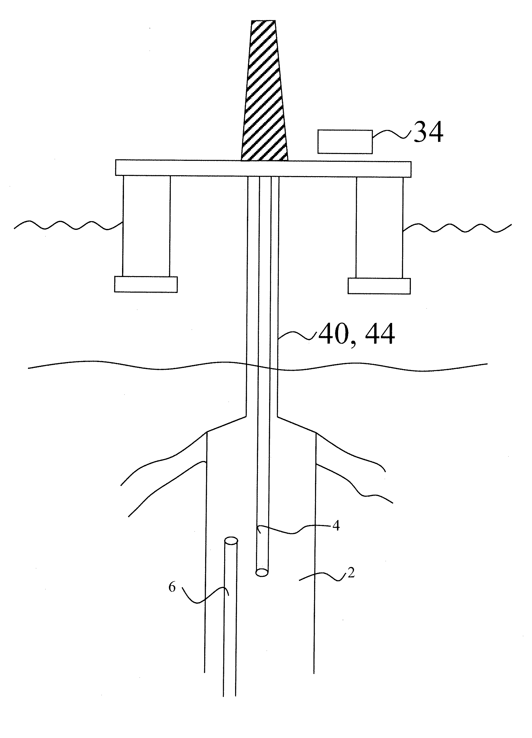
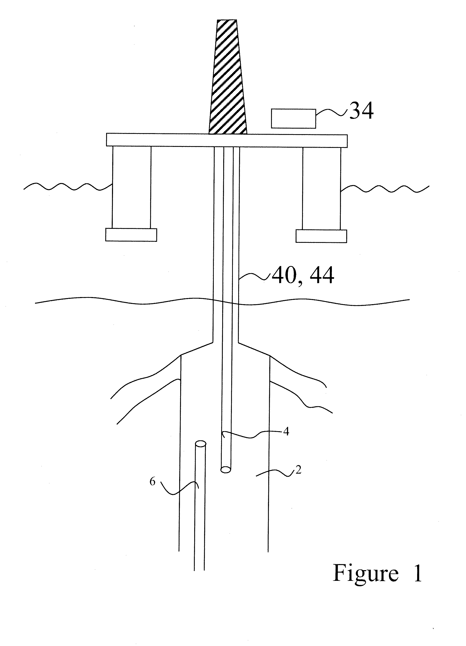
[0043]FIG. 1 shows a simplified view of a radiating cable system of the present invention arranged within a production tubing of a hydrocarbon extraction facility. The radiating cable system 2 comprises a first radiating cable 4 and a second radiating cable 6 made generally of a first and second elongated radiating co-axial axially extending cable. First and second radiating cables 4, 6 are generally flexible in nature and as will described later for allowing general manipulation during insertion and removal into and out of hydrocarbon production tubing. In the current application, a radiating cable is defined as controlled radiation of a signal passed along the length of a cable. In one example embodiment a first elongated radiating cable for coupling signals to a second radiating cable has its shield formed by winding a conductive tape in a helical arrangement with slots between turns to allow controlled leakage of signals as it propagates along the cable.

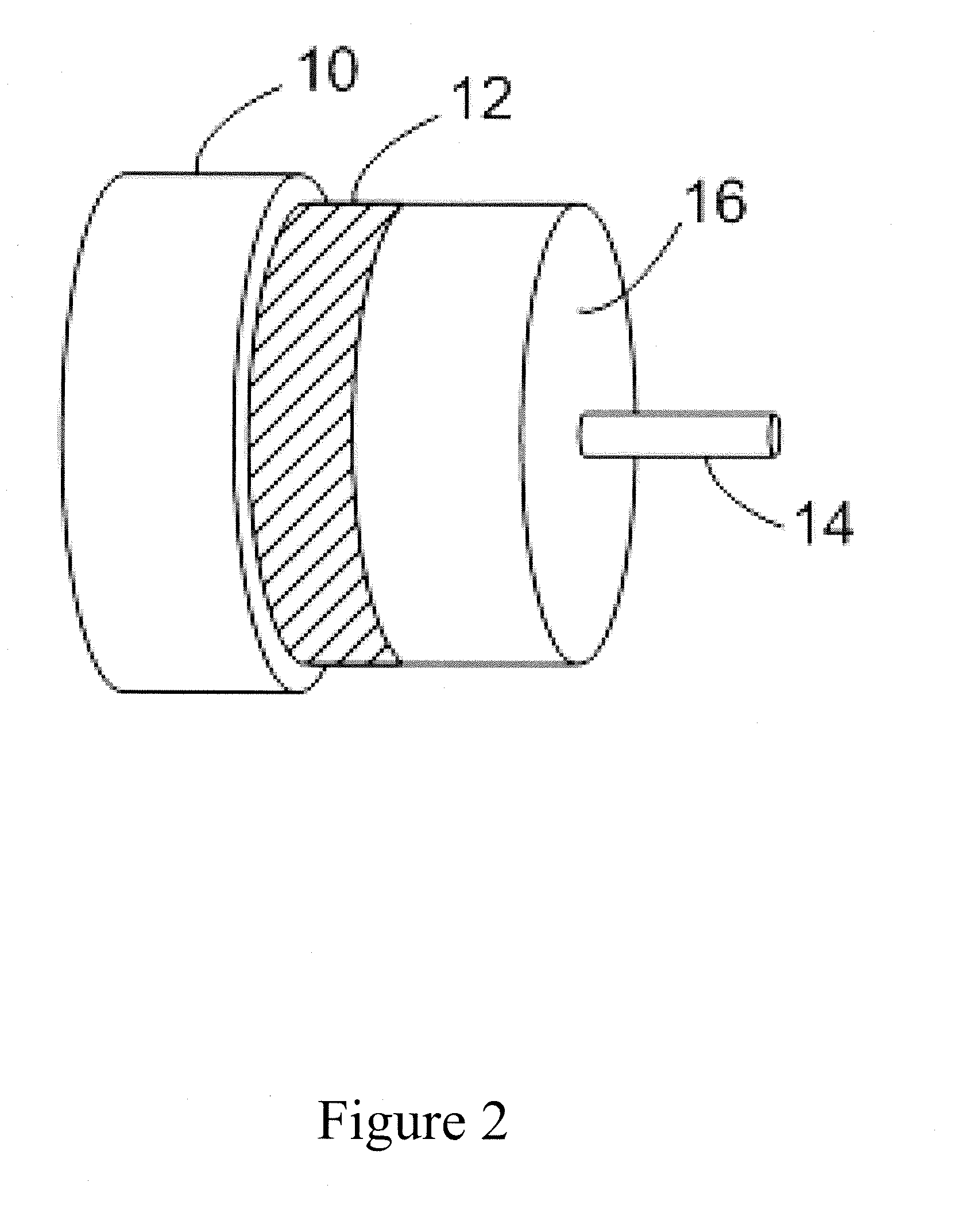
[0044]Similarly, second r...


PUM


Abstract

A pipeline instrumentation and control system comprising a first electrically insulated radiating cable for controlled radiation and reception of electromagnetic signaling carried to a second electrically insulated radiating cable wherein first and second electrically insulated radiating cables are axially disposed along a production well pipe and wherein first axially radiating cable comprises a section configured to substantially overlap second radiating cable section and further wherein electrical signals present in first radiating cable section is configured to induce a corresponding signal in said second radiating cable section to facilitate the transfer of electromagnetic radiation therebetween. The present invention provides reliable data communication from any location within the production system and improves reservoir management, well planning and resource exploitation.

Description

CROSS-REFERENCE TO RELATED APPLICATIONS[0001]This application claims the benefit of GB 1010095.6 filed Jun. 16, 2010, which application is fully incorporated herein by reference.FIELD OF THE INVENTION[0002]The present invention relates to a radiating cable for the transfer of data signals in a confined space. More particularly, the present invention relates to a leaky radiating cable for the transfer of signals within a pipe structure. Further, the invention relates to a method for providing signal coupling between a first transmission line and a second transmission line e.g. for a hydrocarbon extraction facility.BACKGROUND OF THE INVENTION[0003]In some industrial applications communications may be required between two pieces of equipment deployed inside a pipe structure. One example of such an application is found in the oil and gas industry. The extraction of hydrocarbons from a well system is a very challenging task with such systems typically comprising a complex network of meta...

Claims


Application Information

Patent Timeline
Patent Type & Authority Applications(United States)
IPC IPC(8): E21B47/09E21B47/00E21B47/12
CPCE21B17/028E21B47/122H04B5/0093H04B5/0037H04B5/0031E21B47/13E21B17/0283F16L25/01H01Q13/203
Inventor HYLAND, BRENDAN PETERVOLANTHEN, MARKJAFFREY, ANDREWRHODES, MARK
Owner WFS TECH
Why Eureka
Try Eureka