Determining resistivity anistotropy and formation structure for vertical wellbore sections

a technology of resistivity anistotropy and formation structure, which is applied in the field of oil and gas well logging, can solve the problems of reducing the accuracy of time-delay errors, slowing down the rate of data acquisition, and affecting the accuracy of data acquisition results

Active Publication Date: 2011-12-22
SCHLUMBERGER TECH CORP
View PDF9 Cites 35 Cited by
  • Summary
  • Abstract
  • Description
  • Claims
  • Application Information

AI Technical Summary

Benefits of technology

[0014]Formation properties in a vertical section of a wellbore are determined by considering the vertical section as consisting of one or more segments. Measurements are obtained with a directional resistivity tool at two or more measurement stations within each segment for which the complex 0th harmonic coefficients for the obtained measurements are non-trivially different from one another. For each such segment, the phase shift and attenuation are determined using the complex 0th harmonic coefficients obtained for that segment and an inversion is performed for the formation properties using the determined phase shift and attenuation for that segment. Formation properties for that segment may be output to a display or memory storage device.
[0015]For certain segments, one or more gain factors may be obtained. The gain factors are used to correct the measured voltages for certain neighboring segments and the corrected voltages inver...

Problems solved by technology

However, using two transmitter coils alternately slows the rate of data acquisition, which can lead to errors due to the time delay between sequential measurements.
Multiplexing slows the rate of data acquisition.
The errors due to time delays are magnified when drilling rates are high.
Another problem associated with conventional propagation resistivity or ARC tools is that the magnetic dipole moments of the transmitters and receivers are oriented axially with respect to the tool axis.
As a result, eve...

Method used


Image

  • Determining resistivity anistotropy and formation structure for vertical wellbore sections
  • Determining resistivity anistotropy and formation structure for vertical wellbore sections
  • Determining resistivity anistotropy and formation structure for vertical wellbore sections

Examples


Embodiment Construction

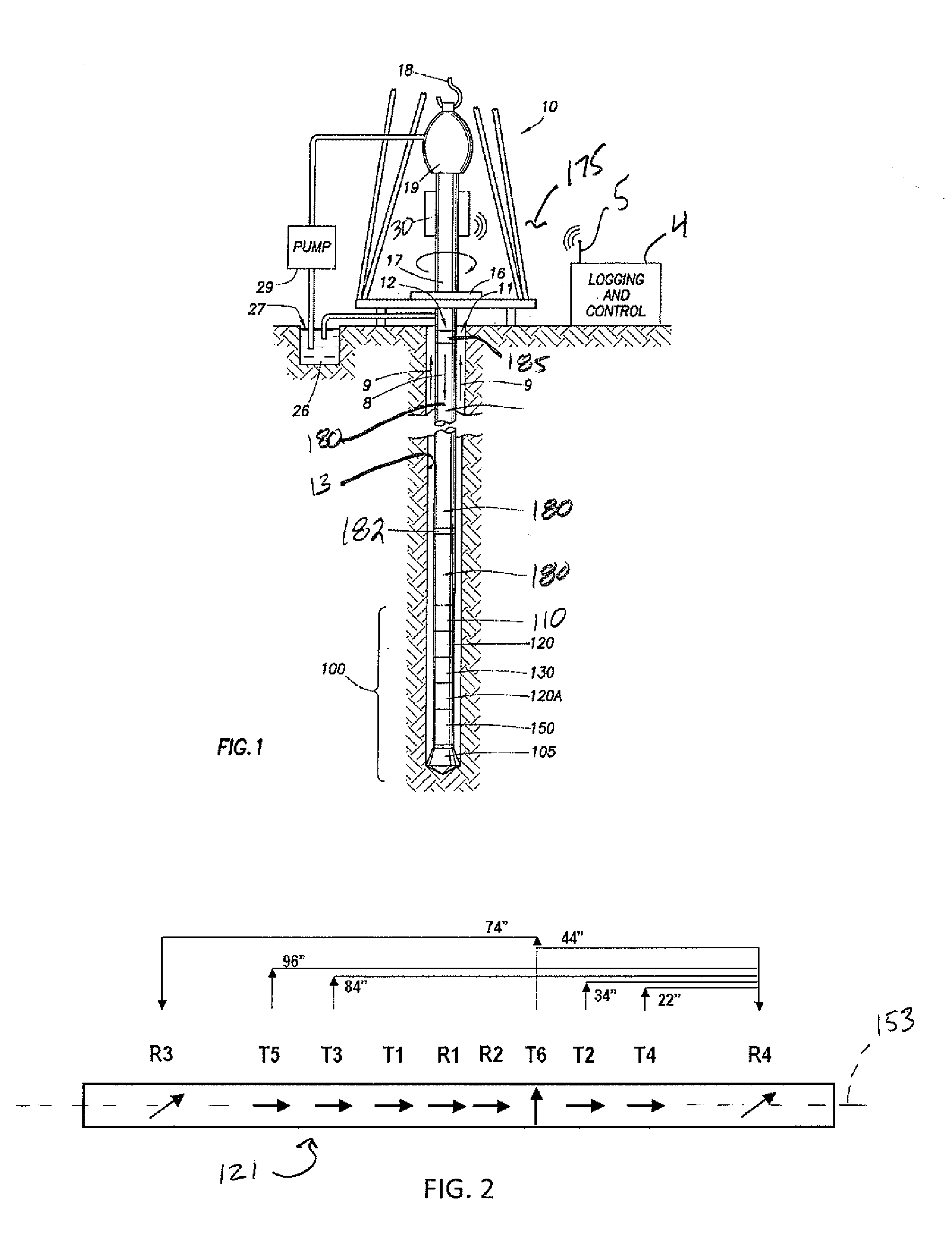
[0024]FIG. 1 illustrates a wellsite system. The wellsite can be onshore or offshore. In this exemplary system, a wellbore 11 is formed in subsurface formations by rotary drilling in a manner that is well known. Directional drilling can also be performed.

[0025]A drill string 12 is suspended within wellbore 11 and has a bottom hole assembly (BHA) 100 that includes a drill bit 105 at its lower end. The surface system includes platform and derrick assembly 10 positioned over the wellbore 11 and the assembly 10 includes a rotary table 16, kelly 17, hook 18, and rotary swivel 19. The drill string 12 is rotated by the rotary table 16, energized by means not shown, that engages the kelly 17 at the upper end of the drill string 12. The drill string 12 is suspended from hook 18, attached to a traveling block (also not shown), and the rotary swivel 19 permits rotation of the drill string 12 relative to the hook. As is well known, a top drive system could alternatively be used.

[0026]The surface...


PUM


Abstract

Formation properties in a vertical section of a wellbore are determined by considering the vertical section as consisting of one or more segments. Measurements are obtained with a directional resistivity tool at two or more measurement stations within each segment for which the complex 0th harmonic coefficients for the obtained measurements are non-trivially different from one another. For each such segment, the phase shift and attenuation are determined using the complex 0th harmonic coefficients obtained for that segment and an inversion is performed for the formation properties using the determined phase shift and attenuation for that segment. Formation properties for that segment may be output to a display or memory storage device. For certain segments, one or more gain factors may be obtained. The gain factors are used to correct the measured voltages for certain neighboring segments and the corrected voltages inverted to obtain anisotropy and formation structure.

Description

CROSS-REFERENCE TO OTHER APPLICATIONS[0001]This application claims priority to and the benefit of U.S. Provisional Application Serial Number 61 / 357,164, filed on Jun. 22, 2010.BACKGROUND[0002]1. Technical Field[0003]This disclosure relates generally to oil and gas well logging, and more specifically, to directional resistivity measurements. Still more specifically, two embodiments of a method are disclosed for determining resistivity anisotropy and formation structure from deep resistivity measurements in vertical wellbore sections. Other measurements are disclosed as well.[0004]2. Description of the Related Art[0005]An alternative to wireline logging techniques is the collection of data on downhole conditions during the drilling process. By collecting and processing such information during the drilling process, the driller can modify or correct key steps of the operation to optimize performance. Schemes for collecting data of downhole conditions and movement of the drilling assembl...

Claims


Application Information

Patent Timeline
IPC IPC(8): G01V3/18
CPCG01V3/28
Inventor YANG, JIAN
Owner SCHLUMBERGER TECH CORP
Why Eureka
Try Eureka