System and device for generating reference signal, and timing signal supply device

a reference signal and timing signal technology, applied in the direction of generating/distributing signals, pulse techniques, instruments, etc., can solve the problems of reducing the frequency stability of the output signal of the oscillator, difficult narrowing of the band of the loop filter of the pll circuit, and only ensuring the opportunity for phase comparison

Inactive Publication Date: 2011-12-22
FURUNO ELECTRIC CO LTD
View PDF4 Cites 12 Cited by
  • Summary
  • Abstract
  • Description
  • Claims
  • Application Information

AI Technical Summary

Benefits of technology

[0035]Thereby, the delay signal is acquired on the reference signal generation device side to corre

Problems solved by technology

However, because the reference signal generation device disclosed in Nonpatent Document 1 is configured to compare the phases of the 1 PPS signal obtained from the GPS and the 1 PPS signal from the voltage-controlled internal crystal oscillator with each other, an opportunity for the phase comparison can only be secured once every second.
Therefore, in a case where an oscillator with comparatively low-grade frequency-temperature characteristics and aging character

Method used


Image

  • System and device for generating reference signal, and timing signal supply device
  • System and device for generating reference signal, and timing signal supply device
  • System and device for generating reference signal, and timing signal supply device

Examples


first embodiment

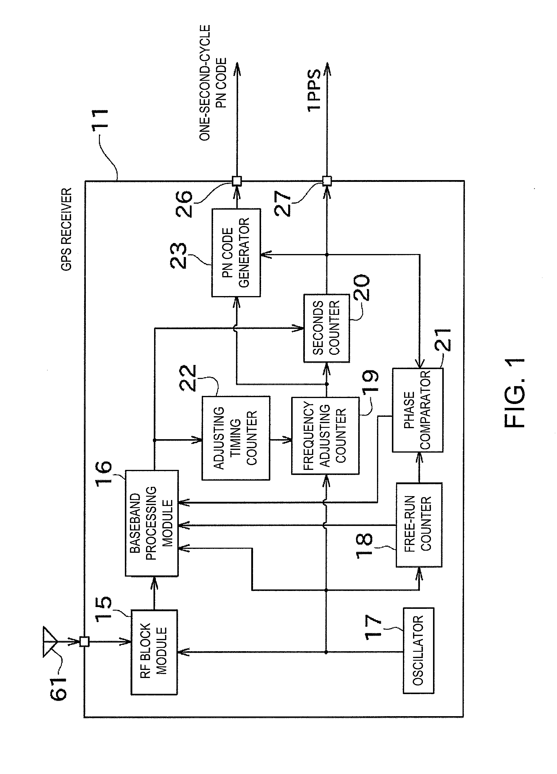
[0044]Next, embodiments of the present invention are described with reference to the drawings. FIG. 1 is a block diagram showing an electrical configuration of a GPS receiver 11 according to the present invention.

[0045]The GPS receiver 11 in FIG. 1 that serves as a timing signal supply device is configured such that a periodic pseudonoise code (PN code) that is repeated every second in the coordinated universal time (UTC), and a 1 PPS signal can be outputted by using a GPS that serves as a global positioning system. The GPS receiver 11 includes a PN code output terminal (spreading code output terminal) 26 for outputting the PN code and a head timing signal output terminal (first timing output terminal) 27 for outputting a pulse signal (the 1 PPS signal) matched with a timing corresponding to the beginning of a code pattern of the PN code.

[0046]In addition, the GPS receiver 11 includes an RF block module 15, a baseband processing module (position calculation module) 16, an oscillator...

second embodiment

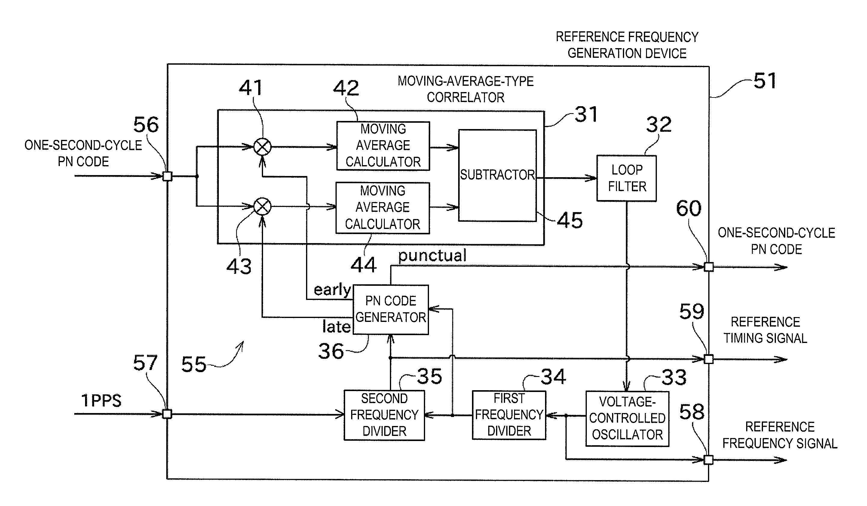
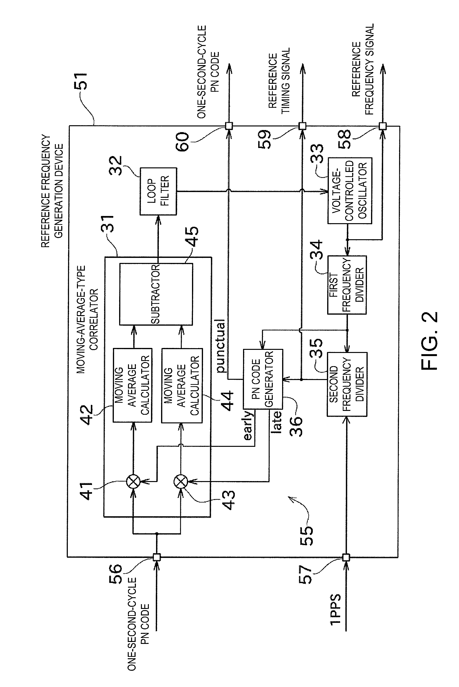
[0106]Next, a configuration of a reference frequency generating system (reference signal generating system) 71 where the GPS receiver 11x and the reference frequency generation device 51x of the second embodiment are combined is described with reference to FIG. 6. The reference frequency generating system 71 includes the GPS receiver 11x and the reference frequency generation device 51x. The reference frequency generating system 71 includes a carrier signal supply source 81, a modulator 82, two multipliers 83 and 84, a voltage-controlled oscillator 85, and a demodulator 86, so as to transmit the one-second-cycle PN code and the various information contained in a data modulation PN code that is outputted from the GPS receiver 11x.

[0107]The carrier signal supply source 81 is constituted with, for example, a commonly-known oscillator and a PLL circuit, and is configured to be able to output a carrier signal to the modulator 82.

[0108]The modulator 82 further modulates the data modulati...


PUM


Abstract

Provided is a timing signal supply device that can frequently perform a phase comparison on a side of receiving a supply of a timing signal and flexibly achieve various operation modes. A GPS receiver 11 includes a baseband processing module 16 and a PN code output terminal 26. The baseband processing module 16 performs a positioning calculation based on positioning signals received from GPS satellites. The PN code output terminal 26 is configured so as to be able to output, based on the result of the positioning calculation by the baseband processing module 16, a PN code that is repeated every second in synchronization with the coordinated universal time.

Description

TECHNICAL FIELD[0001]The present invention generally relates to a system for generating a reference signal by using a timing signal supply device for providing a timing signal utilizing a global positioning system.BACKGROUND ART[0002]This kind of timing signal supply device is disclosed in, for example, Patent Document 1. A GPS receiver disclosed in Patent Document 1 is used for system synchronization in a CDMA mobile communication network and configured to provide timing signals of TOD (Time of Date), 1 PPS (One Pulse per Second) and 10 MHz to a base-station system. With this configuration, the signals received from GPS satellites through a GPS antenna are inputted to the GPS receiver through a coaxial cable, and the GPS receiver demodulates these signals and creates the timing signals of TOD, 1 PPS and 10 MHz.[0003]The configuration referred to as the “GPS receiver” (reference signal generation device) in Patent Document 1 is disclosed in, for example, Nonpatent Document 1. The re...

Claims


Application Information

Patent Timeline
IPC IPC(8): H03K3/00
CPCG01S19/14H04B2201/70715H04B2001/70706
Inventor MIYAHARA, KAZUNORI
Owner FURUNO ELECTRIC CO LTD
Why Eureka
Try Eureka