Gapped Magnet Core

Inactive Publication Date: 2011-12-22
ABB POWER GRIDS SWITZERLAND AG +1
View PDF13 Cites 12 Cited by
  • Summary
  • Abstract
  • Description
  • Claims
  • Application Information

AI Technical Summary

Benefits of technology

[0021]According to one embodiment of the invention, the mould is provided with a common gate for several gaps between adjacent core elements, and at least one core element is provided with a through hole to connect the gaps on both sides of the core element. By providing at least one core element with a through hole, it is possible to use a simple mould wit

Problems solved by technology

The machining of the ceramic spacers is difficult and expensive, and assemblage of the core leg segment by segment is very time-consuming.
Moreover, the great number of manual manufacturing steps is leading to decreased precision of the construction caus

Method used


Image

  • Gapped Magnet Core
  • Gapped Magnet Core
  • Gapped Magnet Core

Examples


Example

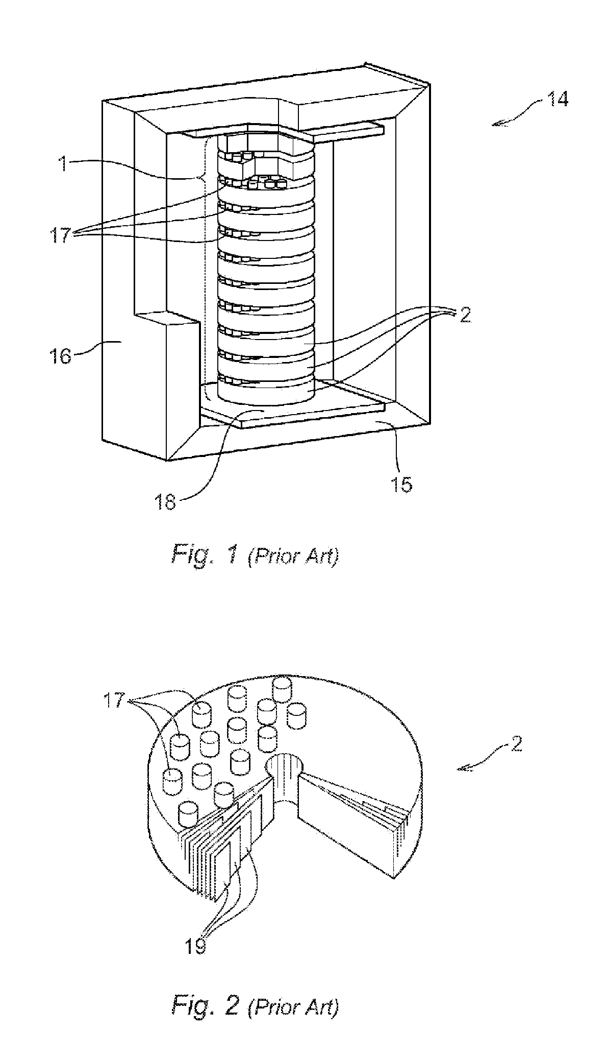
[0030]In a prior art shunt reactor core frame 14 of FIG. 1, a gapped core leg 1 is positioned between two yokes 15 and two side legs 16. The core leg 1 comprises a plurality of core elements 2 arranged in a stacked manner. The core elements 2 are spaced apart by a large number of cylinder-shaped ceramic spacers 17 provided in each gap between adjacent core elements 2. The magnetic connection between the yokes 15 and the core leg 1 is obtained via so-called cross flux plates 18. The core elements 2 comprise radial laminated core steel sheets 19 according to FIG. 2, the lamination blocks being moulded in epoxy resin to form solid pieces. The ceramic spacers 17 are glued on one face of the core elements 2 before stacking the core elements 2.

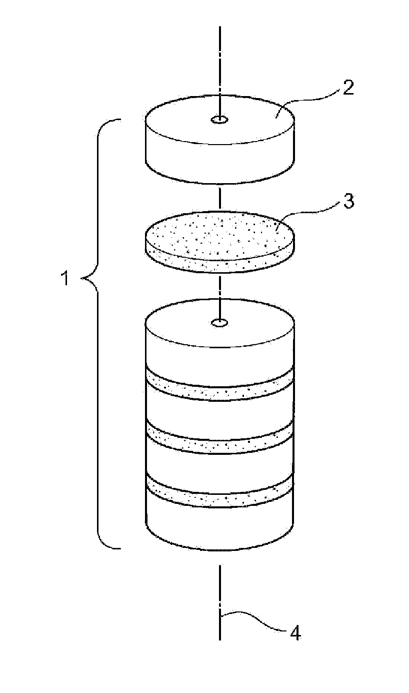
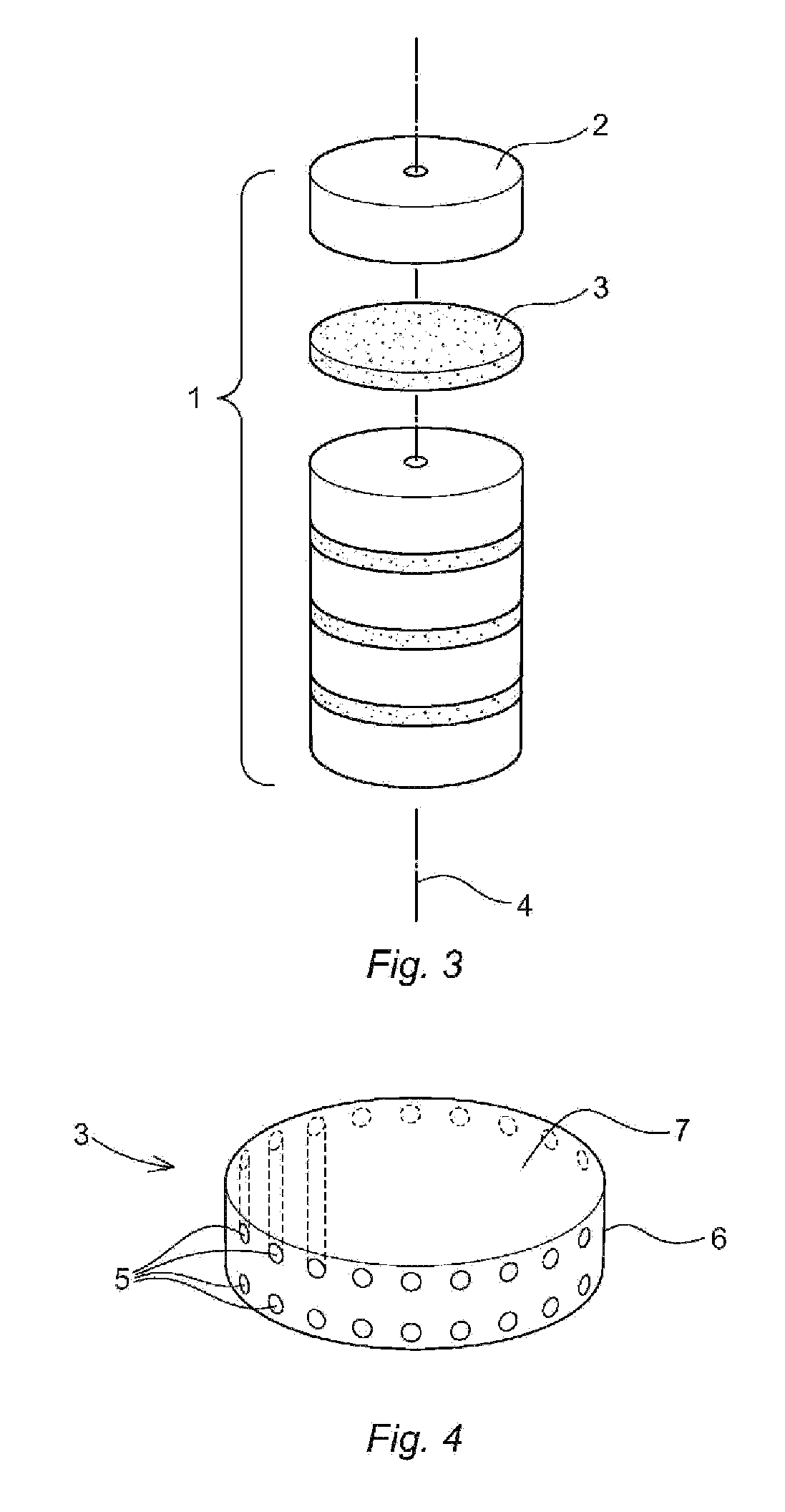
[0031]FIG. 3 shows a gapped core leg 1 according to one embodiment of the invention with a plurality of core elements 2 being separated by direct cast spacers 3. In FIG. 3 one of the direct cast spacers 3 appears to be loose, but this is only for th...


PUM

PropertyMeasurementUnit
Distanceaaaaaaaaaa

Abstract

A gapped core leg for a shunt reactor, comprising magnetic core elements separated by spacers cast directly between the core elements. Accordingly, a rigid core leg construction is achieved.

Description

CROSS-REFERENCE TO RELATED APPLICATIONS[0001]The present application is a continuation of pending International patent application PCT / EP2009 / 067323 filed on Dec. 16, 2009 which designates the United States and claims priority from European patent application 09150901.8 filed on Jan. 20, 2009, the content of which is incorporated herein by reference.FIELD OF THE INVENTION[0002]The present invention relates to a core leg for a shunt reactor, wherein magnetic core elements of the leg are separated by spacers between the core elements. The present invention also relates to manufacturing of a core leg with spacers.BACKGROUND OF THE INVENTION[0003]A shunt reactor is an inductive device which has an important function of compensating capacitive generation in a high voltage power transmission system. In a gapped core type of reactor a subdivided core leg comprising magnetic core elements is provided inside the reactor winding. This core leg functions as a carrier and director of the magnet...

Claims


Application Information

Patent Timeline
IPC IPC(8): H01F27/24H01F7/06
CPCH01F3/14H01F27/08Y10T29/49075H01F37/00H01F41/0206H01F27/263
Inventor ANGER, JANFORSLIN, JULIAGAFVERT, UNO
Owner ABB POWER GRIDS SWITZERLAND AG
Why Eureka
Try Eureka