
Solid state lighting device and method employing heat exchanger thermally coupled circuit board

a heat exchanger and circuit board technology, applied in the field of illumination, can solve the problems of high cost low thermal conductivity of electrically non-conductive heat exchangers, and inability to provide as high thermal conductivity of typical adhesives

Active Publication Date: 2011-12-22
EXPRESS IMAGING SYST
View PDF13 Cites 90 Cited by
  • Summary
  • Abstract
  • Description
  • Claims
  • Application Information

AI Technical Summary

Benefits of technology

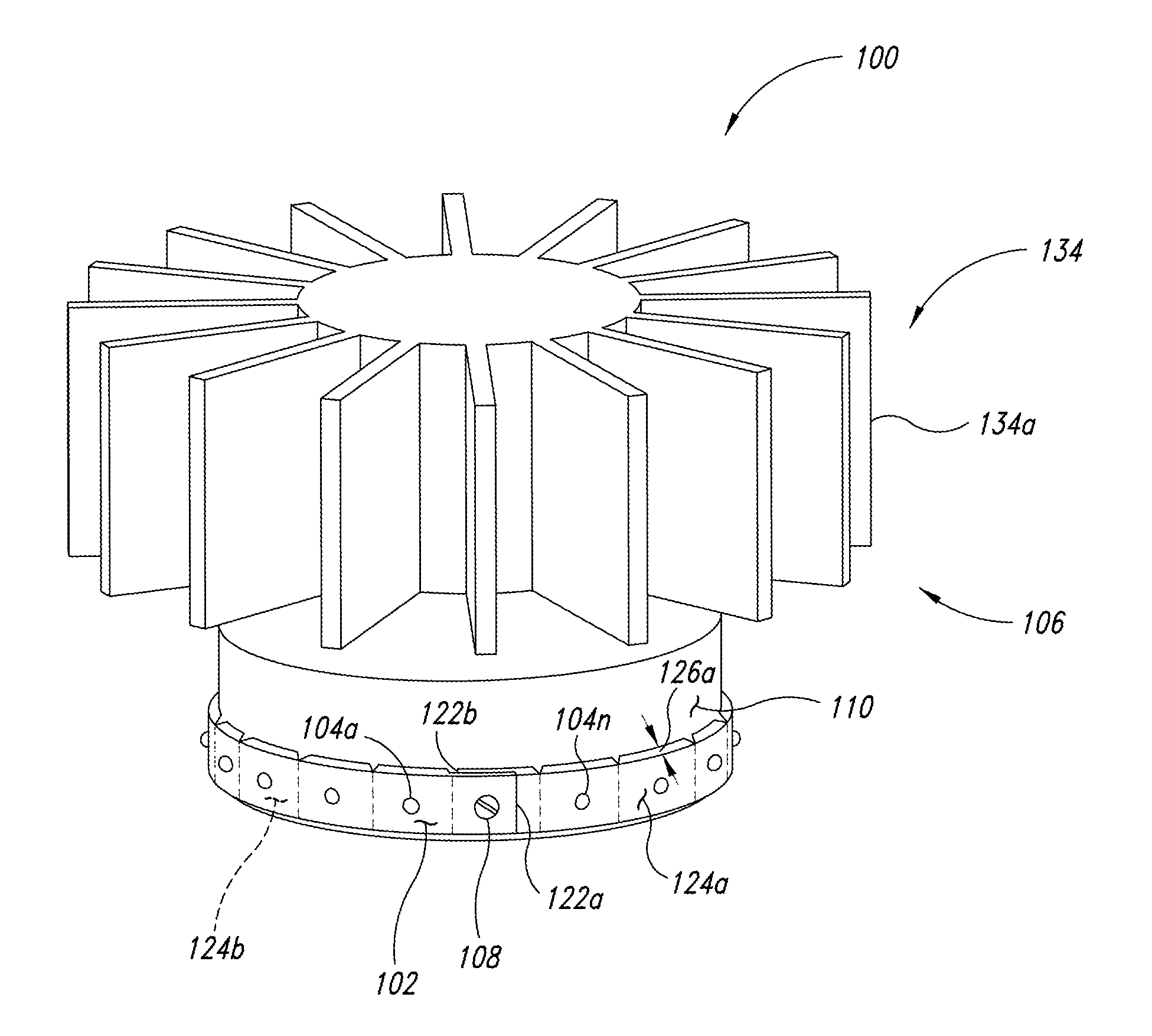
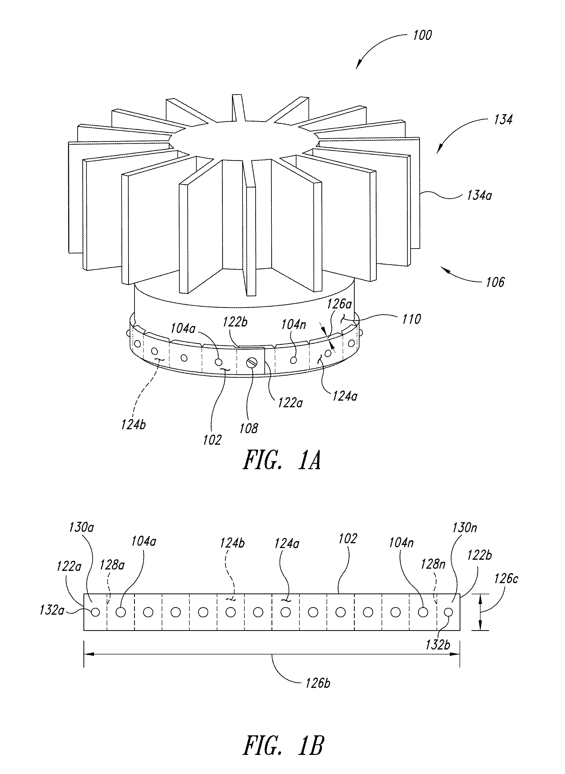
[0018]A method of constructing a lighting device may be summarized as including providing a heat exchanger having a circuit board mounting face having a longitudinal dimension and a lateral dimension and a plurality of fins, the circuit board mounting face being curved along at least one of the longitudinal dimension or the lateral dimension thereof; providing at least one circuit board having a number of kerfs and a number of flats separate by the kerfs, the circuit board having a longitudinal dimension and a lateral dimension, the circuit board carrying at least two solid state light emitters positioned at the flats between the kerfs; and removably physically coupling the circuit board to the heat exchanger under at least one of a tensile or a compressive force with at least one fastener such that the first circuit board is curved along at least one of the longitudinal dimension or the lateral dimension of the circuit board when the circuit board is physically coupled to the heat exchanger by the at least one fastener.
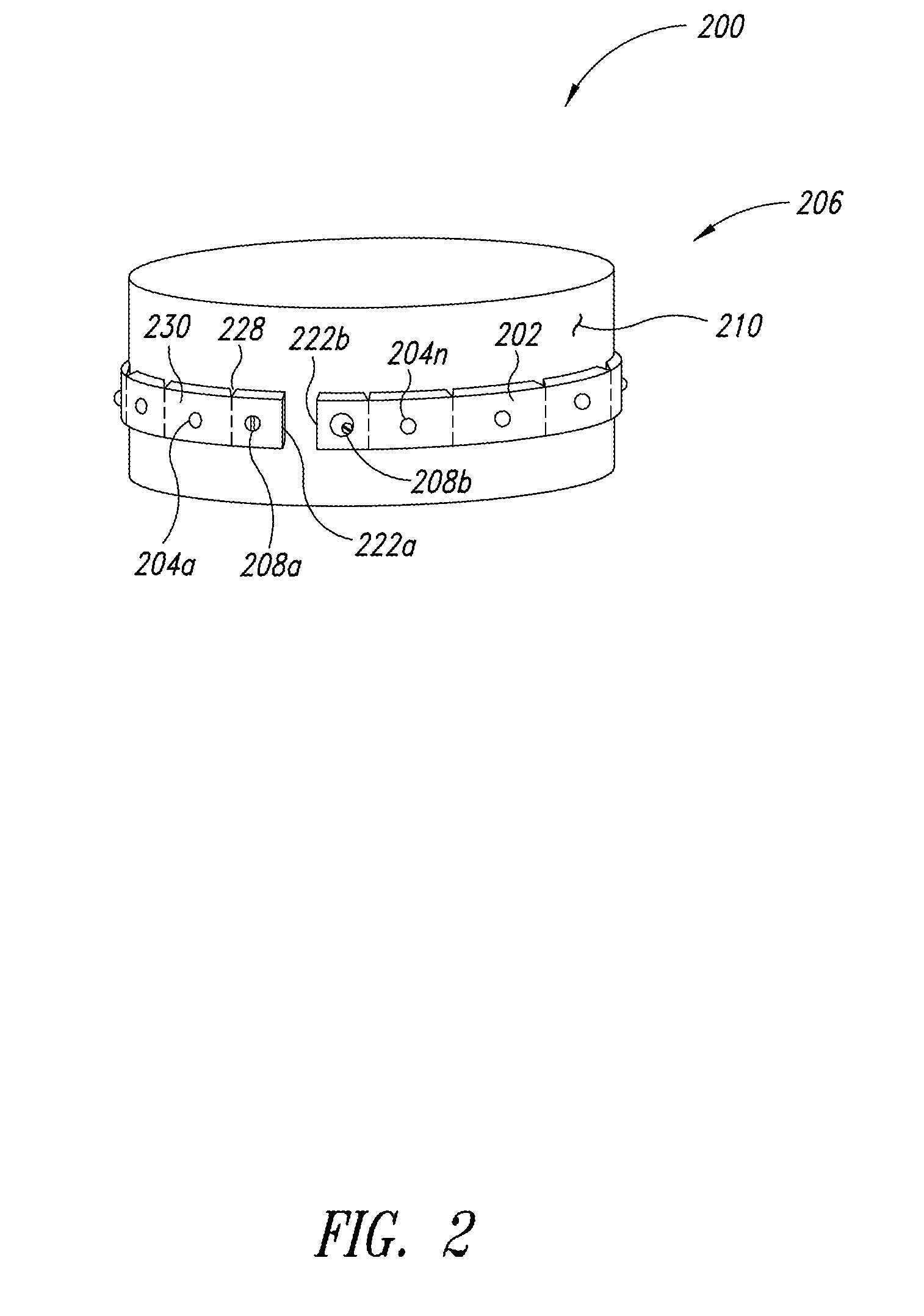
[0019]Removably physically coupling the circuit board to the heat with at least one fastener may include removably physically coupling the circuit board to the heat with a single fastener. Removably physically coupling the circuit board to the heat with at least one fastener may include removably physically coupling the circuit board to the heat with a cam fastener that applies at least one of an additional tensile force or an additional compressive force to the circuit board when the circuit board is physically coupled to the heat exchanger by the at least one cam fastener. Removably physically coupling the circuit board to the heat with at least one fastener may include removably physically coupling the circuit board to the heat with a peripheral clamp.

Problems solved by technology

However, electrically non-conductive heat exchangers tend to have very low thermal conductivity relative to electrically conductive heat exchangers.
Electrically non-conductive heat exchangers are also typically more expensive than electrically conductive heat exchangers.
The large number of solid-state light sources required to achieve a desired level of illumination means that a large number of screws are typically required to fasten the PCB tightly enough to the heat exchanger to obtain the desired level of thermal conduction.
Such an approach suffers from a number of drawbacks: For example, typical adhesives do not provide as high a thermal conductivity as compared to liquid silicone thermal interface materials or thermal interface pads made of silicone or graphite.
Also, adhesives are typically not electrically insulating, unlike silicone thermal pads.
Additionally, the PCB is not easily removable for servicing or replacement if one or more LEDs is damaged, out of specification or fails.

Method used


Image

  • Solid state lighting device and method employing heat exchanger thermally coupled circuit board
  • Solid state lighting device and method employing heat exchanger thermally coupled circuit board
  • Solid state lighting device and method employing heat exchanger thermally coupled circuit board

Examples


Embodiment Construction

[0036]In the following description, certain specific details are set forth in order to provide a thorough understanding of various disclosed embodiments. However, one skilled in the relevant art will recognize that embodiments may be practiced without one or more of these specific details, or with other methods, components, materials, etc. In other instances, well-known structures associated with lighting fixtures, power supplies and / or power system for lighting have not been shown or described in detail to avoid unnecessarily obscuring descriptions of the embodiments.

[0037]Unless the context requires otherwise, throughout the specification and claims which follow, the word “comprise” and variations thereof, such as, “comprises” and “comprising” are to be construed in an open, inclusive sense that is as “including, but not limited to.”

[0038]Reference throughout this specification to “one embodiment” or “an embodiment” means that a particular feature, structure or characteristic desc...


PUM

PropertyMeasurementUnit
thicknessaaaaaaaaaa
depthaaaaaaaaaa
widthaaaaaaaaaa

Abstract

An illumination device comprises a circuit board that carries solid-state light sources and a heat transfer structure to which the circuit board is intimately physically coupled such that the circuit board is curved along at least one of a longitudinal dimension or a lateral dimension thereof. Such may allow less fasteners to be used than would otherwise be possible, while maintaining close contact over a large portion of the surface area. Some embodiments may employ a clamp, for example a peripheral clamp such as a cover or bezel clamp.

Description

CROSS REFERENCE TO RELATED APPLICATION[0001]This application claims benefit under 35 U.S.C. 119(e) of U.S. Provisional Patent Application Ser. No. 61 / 357,421, filed Jun. 22, 2010, which is incorporated herein by reference in its entirety.BACKGROUND[0002]1. Technical Field[0003]This disclosure generally relates to illumination, and more particularly to apparatus and methods that employ a heat exchanger to cool solid-state light sources.[0004]2. Description of the Related Art[0005]With increasing trend of energy conservation and for various other reasons, solid-state lighting has become more and more popular as the source of illumination in a wide range of applications. As generally known, solid-state lighting refers to a type of lighting that emits light from a solid-state materials, such as a block of semiconductor material. Such contrasts with more traditional forms of lighting, for example incandescent or fluorescent lighting which typically employ a filament in a vacuum tube or a...

Claims


Application Information

Patent Timeline
Patent Type & Authority Applications(United States)
IPC IPC(8): F21V29/00F21V11/00H05K3/00F21S4/00
CPCF21V19/0055Y10T29/49124F21Y2101/02F21Y2103/022F21Y2111/004F21Y2111/005H05K1/0203H05K1/0278H05K3/0061H05K2201/09018H05K2201/09027H05K2201/10106H05K2201/10409F21S8/08F21V7/0058F21V7/041F21V13/02F21V19/0035F21V29/777F21W2131/103F21Y2115/10F21Y2103/33F21Y2107/20F21Y2107/30
Inventor RENN, JOHN O.REED, WILLIAM G.LARSEN, BRADLEY B.
Owner EXPRESS IMAGING SYST
Learn More