Egr control apparatus for internal combustion engine

a control apparatus and internal combustion engine technology, applied in the direction of electric control, machines/engines, instruments, etc., can solve the problems of short or excessive ratio of inert gas supplied to the cylinders, unstable combustion state of the engine, increased exhaust emissions, etc., to achieve accurate control of inert gas amount, reduce exhaust emissions, and stable combustion state

Active Publication Date: 2011-12-22
HONDA MOTOR CO LTD
View PDF15 Cites 21 Cited by
  • Summary
  • Abstract
  • Description
  • Claims
  • Application Information

AI Technical Summary

Benefits of technology

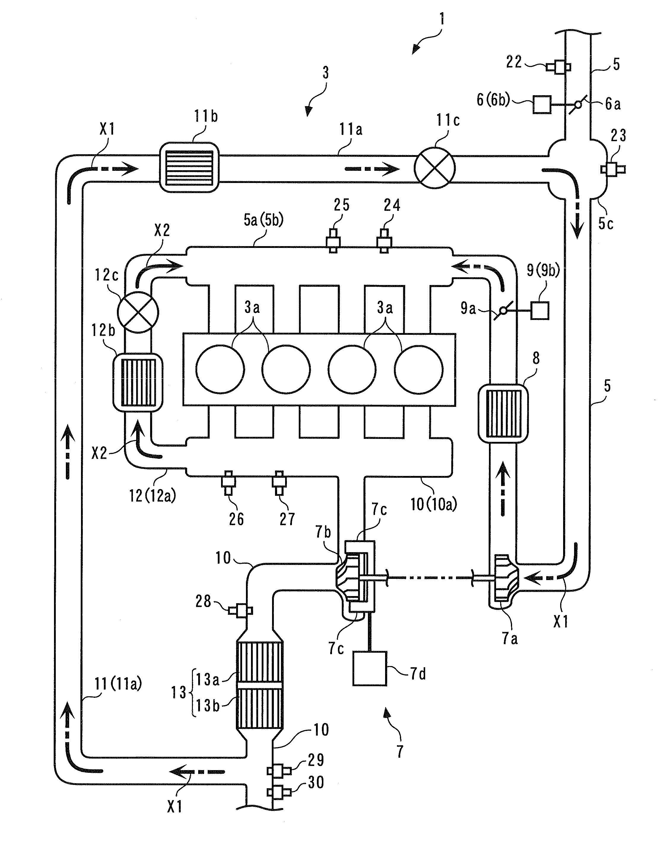
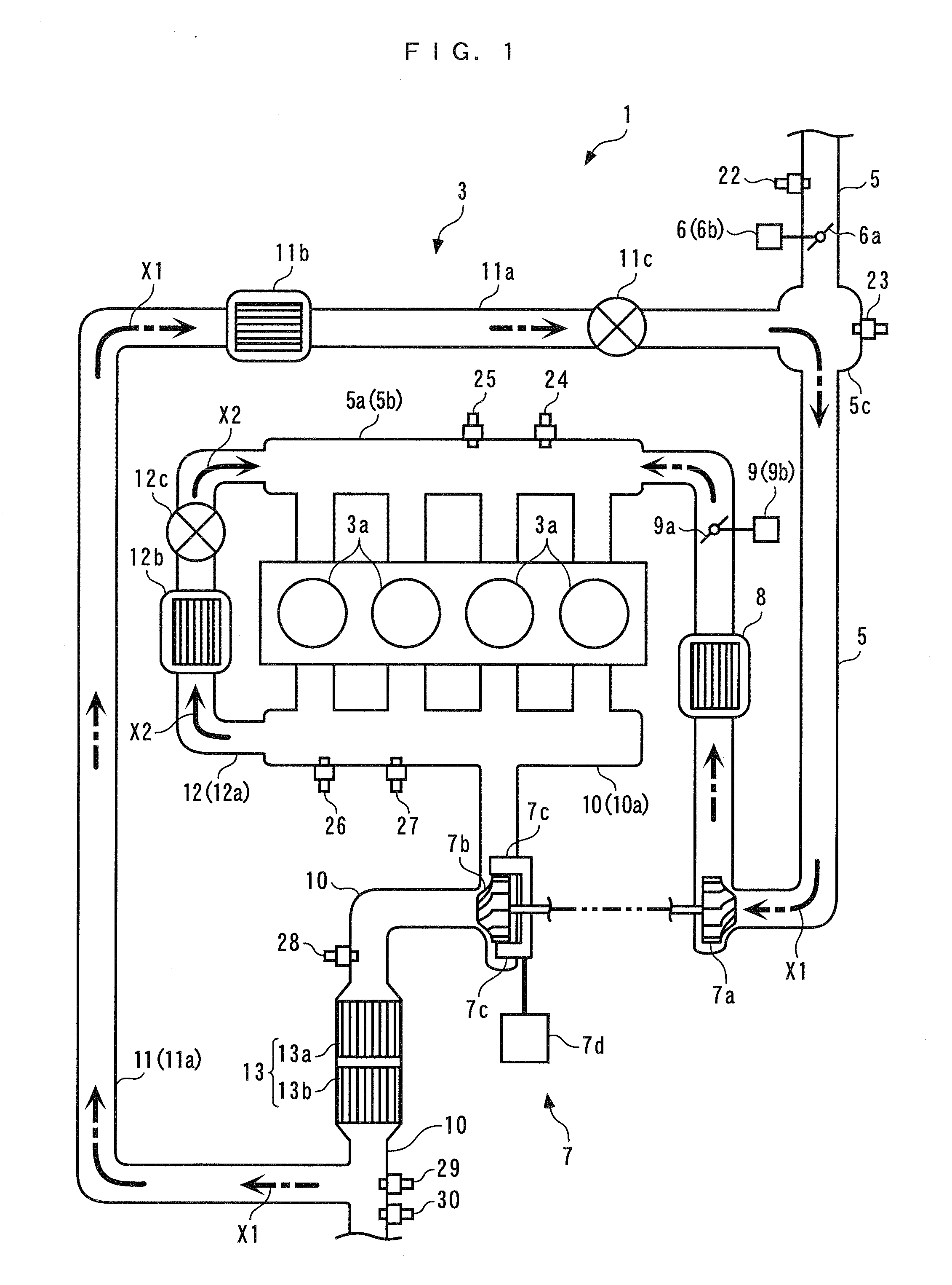
[0008]It is an object of the present invention to provide an EGR control apparatus for an internal combustion engine, which is capable of accurately controlling an inert gas amount and an inert gas ratio of two types of EGR gas supplied to cylinders of the engine via two paths different from each other, thereby making it possible to ensure a stable combustion state and reduced exhaust emissions.

Problems solved by technology

However, when the amount of the EGR gas is controlled without taking the above fact into account, as in the EGR control apparatus disclosed in Japanese Laid-Open Patent Publication (Kokai) No. 2004-150319, the amount (or ratio) of inert gas supplied to the cylinders becomes short or excessive, which can make the combustion state of the engine unstable or result in increased exhaust emissions.
However, according to the above-described conventional EGR control apparatus, the EGR control is performed such that in the low-to-medium speed and low-to-medium load region, the high-pressure EGR gas is mainly recirculated, and the insufficient amount thereof is supplemented with the low-pressure EGR gas, which can make the amount of the inert gas in the cylinders short or excessive due to the above-mentioned dead time characteristic of the low-pressure EGR gas.

Method used


Image

  • Egr control apparatus for internal combustion engine
  • Egr control apparatus for internal combustion engine
  • Egr control apparatus for internal combustion engine

Examples


first embodiment

]FIG. 26 is a timing diagram showing an example of results of a simulation in a case where the models are configured such that there is a modeling error in the EGR control by the EGR control apparatus ;

[0050]FIG. 27 is a timing diagram showing, for comparison, an example of results of a simulation in the case where the models are configured such that there is a modeling error, when the equation for calculating the target high-pressure inert gas flow rate dGiegr_HP_cmd is changed;

[0051]FIG. 28 is a timing diagram showing an example of results of a simulation in a case where an equation for calculating an error EVNS is changed and models are configured such that there is a modeling error, in the EGR control by the EGR control apparatus according to the first embodiment;

second embodiment

[0052]FIG. 29 is a block diagram of an inert gas-estimating section of an EGR control apparatus ;

[0053]FIG. 30 is a schematic diagram of a hierarchical neural network used in the inert gas-estimating section of according to the second embodiment; and

[0054]FIG. 31 is a flow chart of an estimated value calculation process according to the second embodiment;


PUM


Abstract

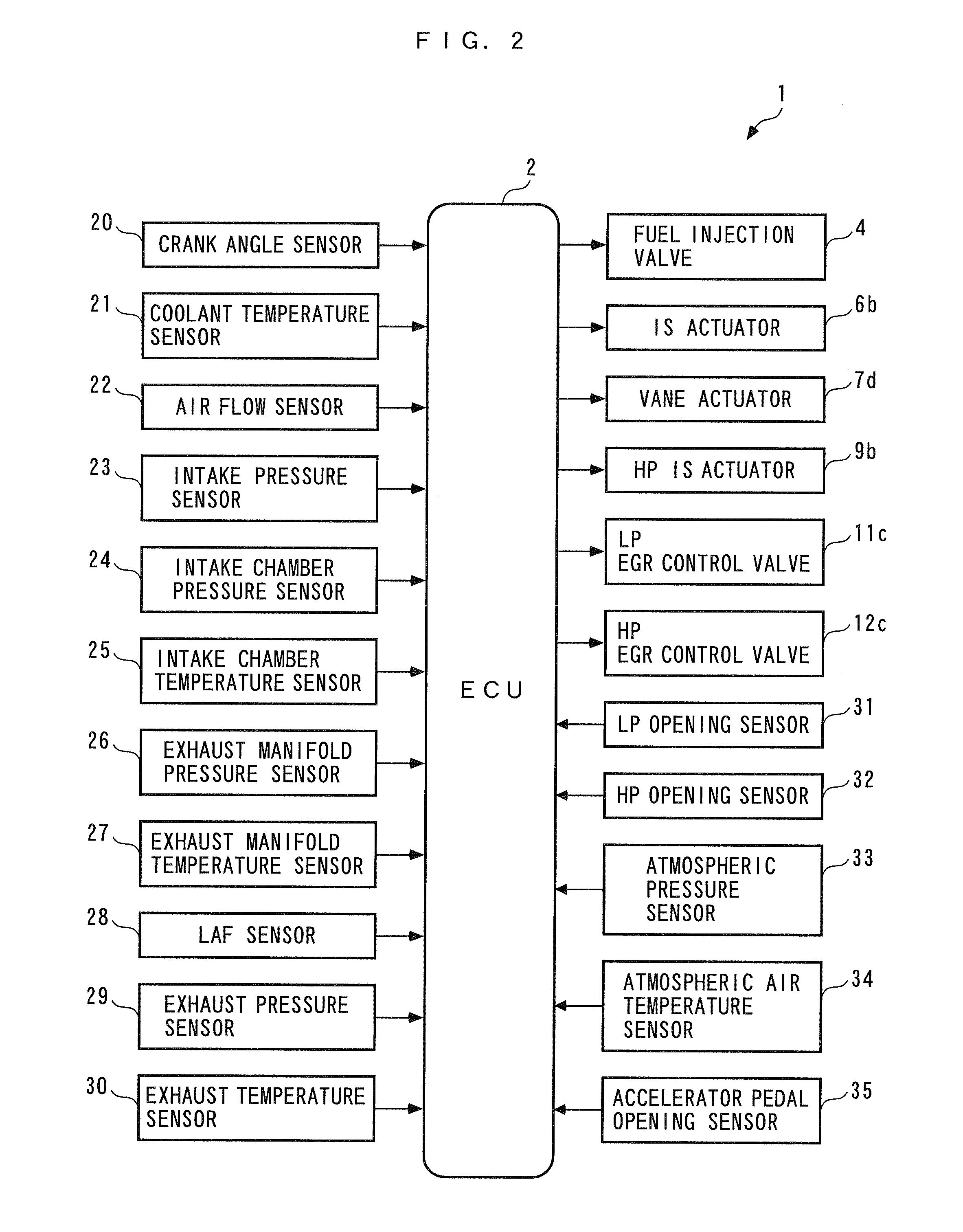
An EGR control apparatus for an internal combustion engine, which is capable of accurately controlling an inert gas amount and an inert gas ratio of two types of EGR gas supplied to cylinders of the engine via two paths different from each other, thereby making it possible to ensure a stable combustion state and reduced exhaust emissions. The EGR control apparatus includes a low-pressure EGR device, a high-pressure EGR device, and an ECU. The ECU calculates a target low-pressure opening, calculates an estimated value of an in-cylinder low-pressure inert gas flow rate, which is the estimated value of an inert gas amount included in low-pressure EGR gas supplied to the cylinders via an intake passage, calculates a target high-pressure opening using the estimated value, and controls low-pressure and high-pressure EGR control valves, using the target low-pressure opening and the target high-pressure opening.

Description

BACKGROUND OF THE INVENTION[0001]1. Field of the Invention[0002]The present invention relates to an EGR control apparatus for an internal combustion engine, which controls the amounts of two types of EGR gas in the engine in which the two types of EGR gas are supplied to cylinders thereof via two paths different from each other.[0003]2. Description of the Related Art[0004]Conventionally, as an EGR control apparatus for an internal combustion engine, one disclosed in Japanese Laid-Open Patent Publication (Kokai) No. 2004-150319 is known. This engine is a diesel engine, and is provided with a turbocharger, a low-pressure EGR device, a high-pressure EGR device, and so forth. The low-pressure EGR device recirculates part of exhaust gases from an exhaust passage on the downstream side of a turbine of the turbocharger and a catalytic device into an intake passage on the upstream side of a compressor of the turbocharger, as low-pressure EGR gas, while the high-pressure EGR device recircula...

Claims


Application Information

Patent Timeline
Patent Type & Authority Applications(United States)
IPC IPC(8): F02D28/00
CPCF02D41/0047Y02T10/47F02D41/0072F02D41/1402F02D41/1405F02D41/1456F02D41/187F02D2009/0272F02D2041/1433F02D2200/0402F02M25/0707F02M25/0709F02M25/0718F02M25/0727F02M25/0744F02D41/0062F02M26/05F02M26/06F02M26/15F02M26/23F02M26/38Y02T10/40
Inventor YASUI, YUJIHASHIMOTO, EIJIHAGA, HISAONAKAJIMA, KOICHI
Owner HONDA MOTOR CO LTD
Why Eureka
Try Eureka