Eureka AIR delivers breakthrough ideas for toughest innovation challenges, trusted by R&D personnel around the world.

Cooling system

Inactive Publication Date: 2011-12-29
HITACHI LTD
View PDF6 Cites 10 Cited by
  • Summary
  • Abstract
  • Description
  • Claims
  • Application Information

AI Technical Summary

Benefits of technology

[0014]The present invention is made in view of the above circumstances, and has an object to provide a cooling system with high energy-saving performance, which reduces running cost by controlling an air blow quantity of the cooling apparatus in accordance with load while preventing a temperature rise of electronic devices, in a cooling system including a cooling apparatus which is installed between racks and performs semi-local cooling operation in a refrigerant natural circulation cycle.
[0020]According to the cooling system, in a semi-local cooling system by natural circulation of the refrigerant, at the time of a partial load, the air blow quantity of the cooling apparatus can be controlled while the rack is prevented from absorbing high-temperature air, and the set value of the condenser refrigerant temperature can be changed in accordance with load while occurrence of dew formation is prevented, whereby air-conditioning equipment with high energy conservation can be provided.

Problems solved by technology

These electronic devices need a constant temperature environment for normal operation, and if the electronic devices are brought into a high-temperature state, they are likely to cause a trouble such as system stoppage.
In recent years, however, the heat generation amount from electronic devices has been steadily increasing with abrupt increase in processing speed and processing capacity of the electronic devices, and the running cost of an air conditioner has been sharply increasing.
For example, if the air blow quantity of the rack exceeds the air blow quantity of the cooling apparatus, the high-temperature exhaust air by the rack comes around the front surface of the rack, and is likely to cause a temperature rise of the electronic devices.

Method used


Image

  • Cooling system
  • Cooling system
  • Cooling system

Examples


modified example

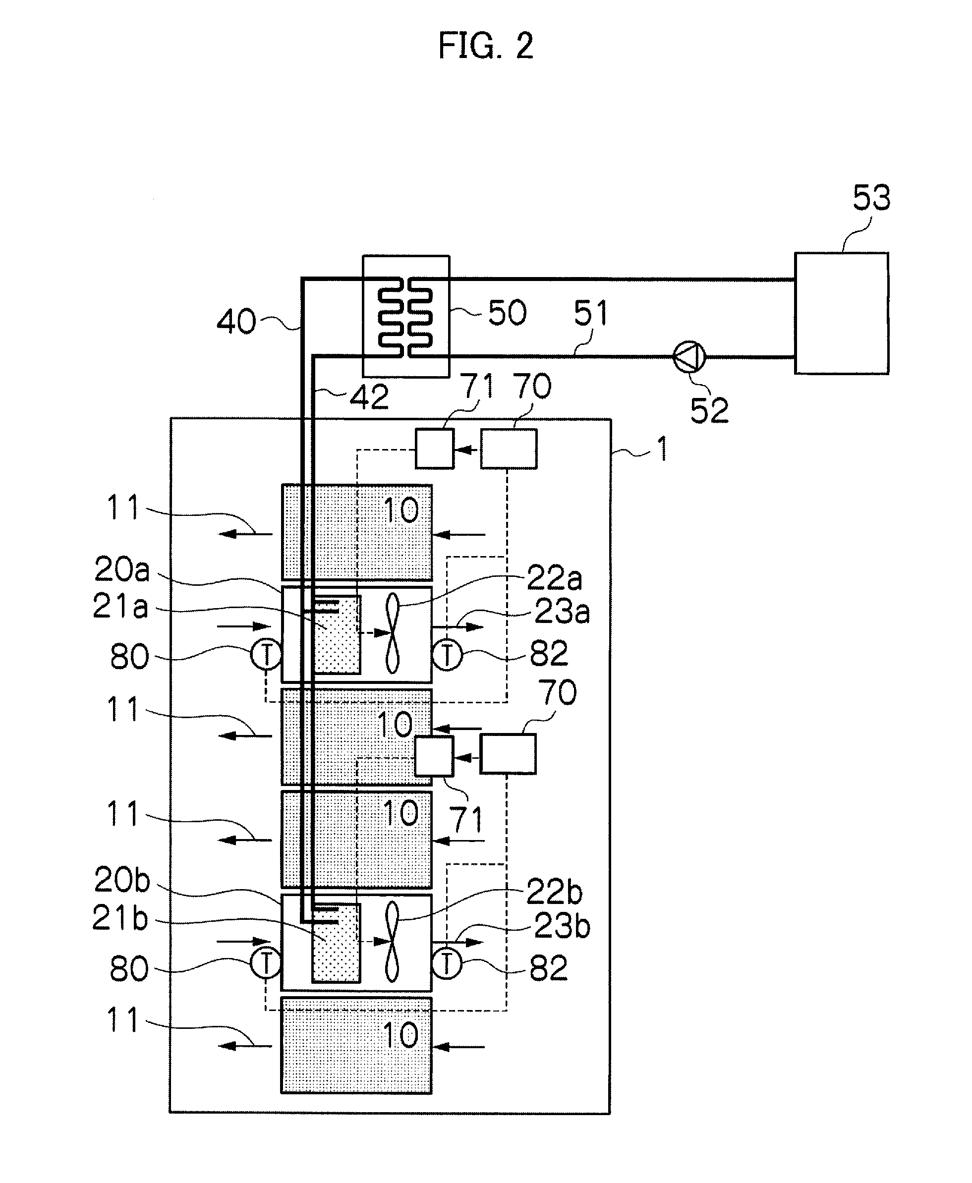
[0044]In each of the cooling systems shown in FIGS. 1 to 5, the condenser 50 which performs heat exchange of cold water and the refrigerant is installed, but a refrigerant cooling tower 55 which condenses the refrigerant by using external air cold heat may be provided instead of the condenser 50 as in FIG. 6.

Air Blow Operation Control Example of the Cooling System of the First Embodiment

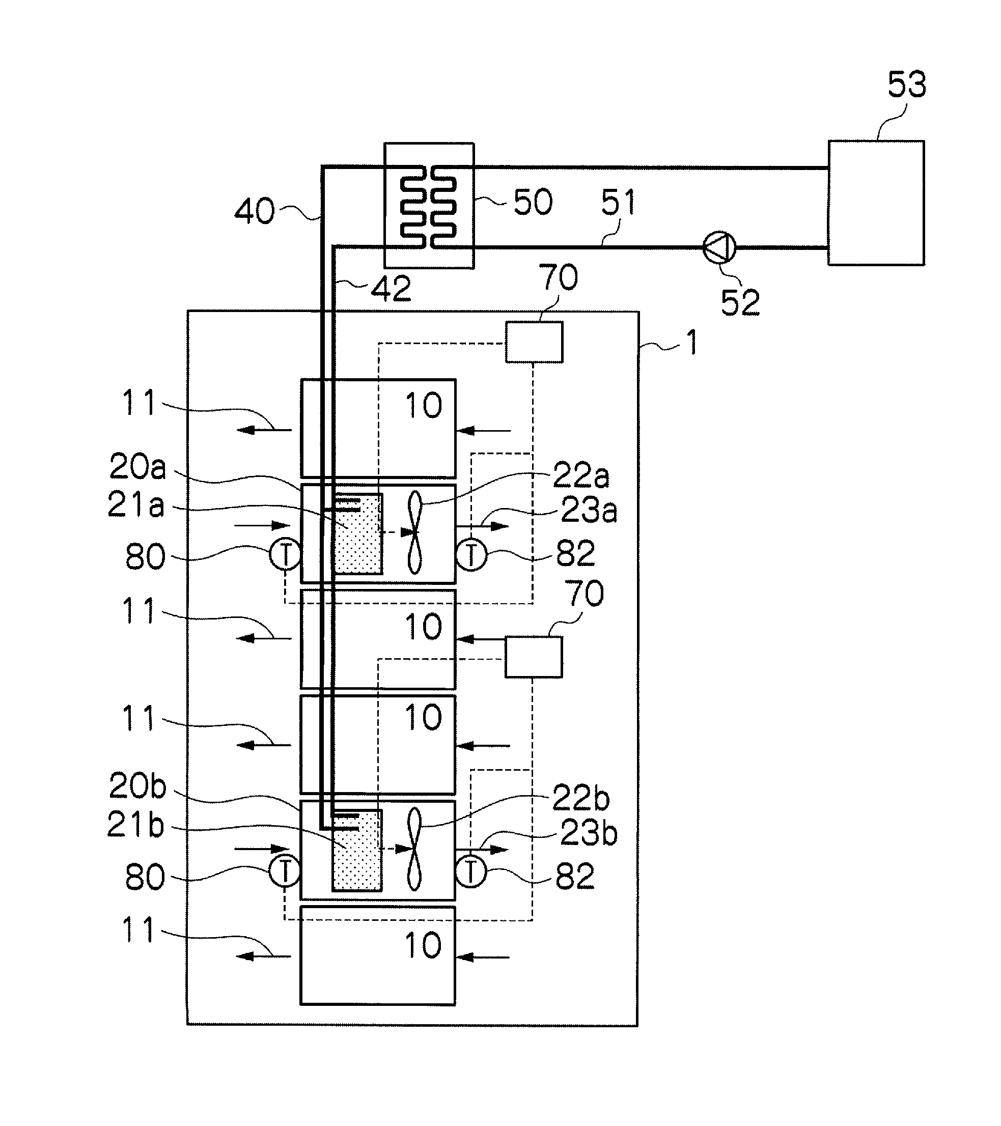
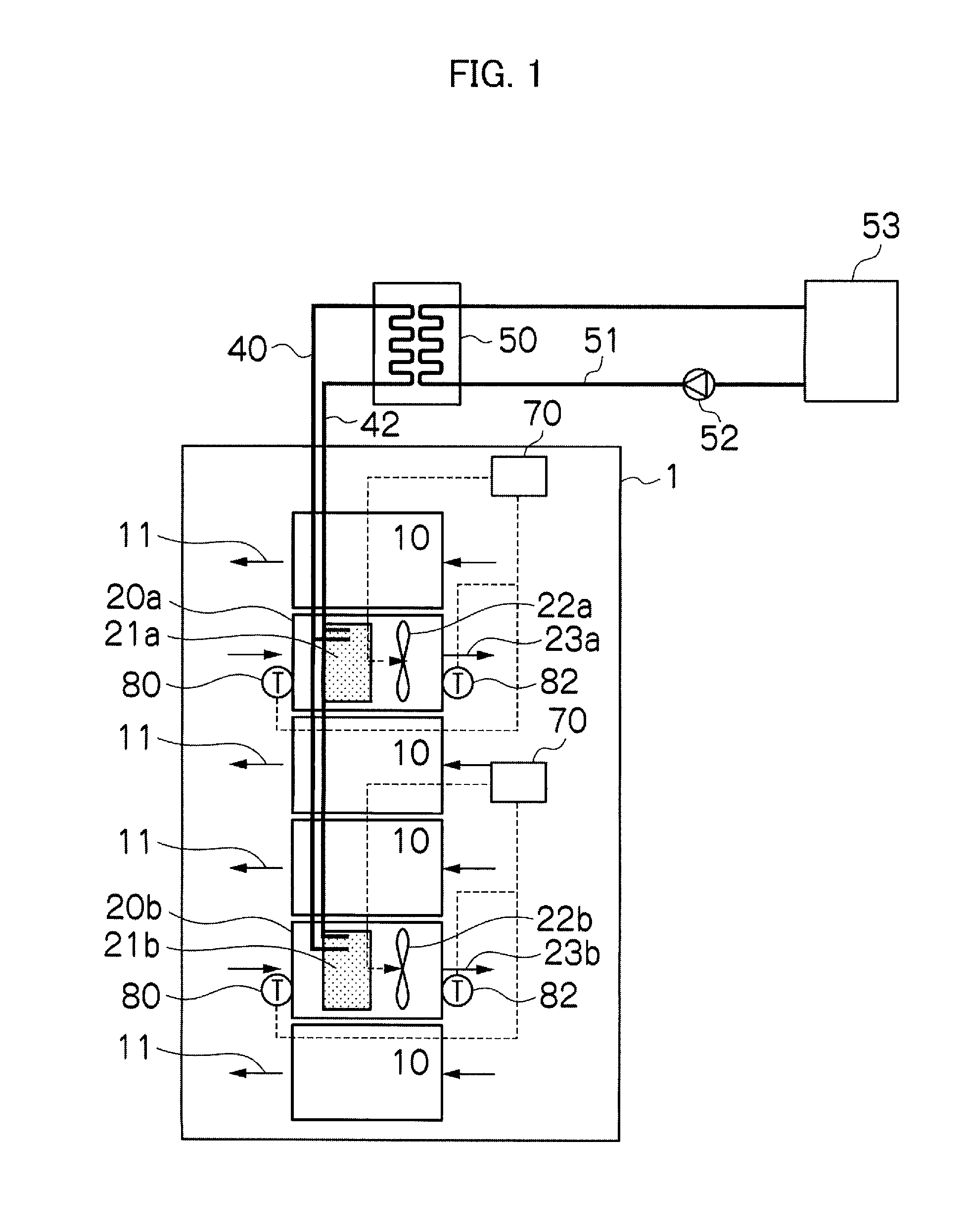
[0045]For example, as shown in FIG. 7, a difference ΔT (ΔT=Tin−Tout) between a measured value Tin of the intake air temperature sensor 80 (see FIG. 1) and a measured value Tout of the return air temperature sensor 82 is calculated, and when the aforesaid temperature difference ΔT is within a range of ΔT1≦ΔT≦ΔT2 where a design maximum temperature difference of the cooling apparatus is set as ΔT1° C., and a design minimum temperature difference is set as ΔT2° C. with respect to the value of the temperature difference ΔT, a blower frequency f corresponding to ΔT is set in advance. Subsequently, at the t...


PUM


Abstract

A cooling system comprising an intake air temperature sensor which measures an intake air temperature to an evaporator by a blower; a return air temperature sensor which measures a return air temperature which is cooled in the evaporator; and a blower frequency switching device which switches a frequency of the blower, wherein the blower frequency switching device controls the frequency of the blower to a frequency of the blower corresponding to a difference between an intake air temperature which is measured by an intake air temperature sensor and a return air temperature which is measured by a return air temperature sensor.

Description

BACKGROUND OF THE INVENTION[0001]1. Field of the Invention[0002]The present invention relates to a cooling system for an electronic device, and particularly to a cooling system for an electronic device which cools heat generated from a plurality of electronic devices such as a computer and a server which are installed in a server room by a cooling apparatus which includes an evaporator and a blower installed between electronic devices.[0003]2. Description of the Related Art[0004]In a server room, a number of electronic devices such as computers and servers are placed in a concentrated state. Electronic devices are generally installed by a rack mount method, that is, a method which stacks electronic devices in layers on racks (casings) according to functional units, and a number of racks are disposed (arranged) in line on the floor of a server room.[0005]These electronic devices need a constant temperature environment for normal operation, and if the electronic devices are brought in...

Claims


Application Information

Patent Timeline
IPC IPC(8): F25D17/06F24F11/76
CPCH05K7/20836H05K7/20818Y02B30/70F24F11/77F24F11/30F24F2110/10H05K7/2059H05K7/2069H05K7/20745H05K7/20827
Inventor ITO, JUNICHIKASHIRAJIMA, YASUHIROINADOMI, YASUHIKOYOSHIDA, TOMOHIRO
Owner HITACHI LTD
Why Eureka
Eureka Blog
Learn More