
Gyroscope sensor circuit

a sensor circuit and gyroscope technology, applied in the direction of acceleration measurement using interia force, turn-sensitive devices, instruments, etc., can solve problems such as errors in measuring acceleration, and achieve the effect of reducing the influence of temperature and reducing the settle tim

Inactive Publication Date: 2011-12-29
SAMSUNG ELECTRO MECHANICS CO LTD
View PDF3 Cites 9 Cited by
  • Summary
  • Abstract
  • Description
  • Claims
  • Application Information

AI Technical Summary

Benefits of technology

[0009]An aspect of the present invention provides a gyroscope sensor circuit capable of maintaining constant amplitude in a driving signal of a gyroscope sensor, decreasing the influence of temperature, and reducing settling time, by using automatic gain control.

Problems solved by technology

However, when the velocity Vx is affected by the temperature characteristics of amass body, errors in measuring acceleration may occur.

Method used


Image

  • Gyroscope sensor circuit
  • Gyroscope sensor circuit
  • Gyroscope sensor circuit

Examples


Embodiment Construction

[0024]Exemplary embodiments of the present invention will now be described in detail with reference to the accompanying drawings. The invention may, however, be embodied in many different forms and should not be construed as being limited to the embodiments set forth herein. Rather, these embodiments are provided so that this disclosure will be thorough and complete, and will fully convey the scope of the invention to those skilled in the art. The same or equivalent elements are referred to by the same reference numerals throughout the drawings.

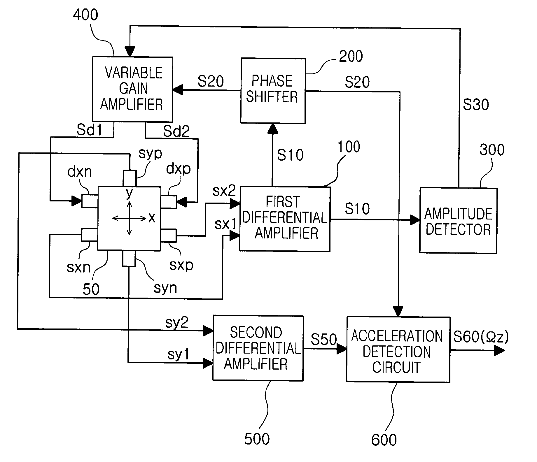
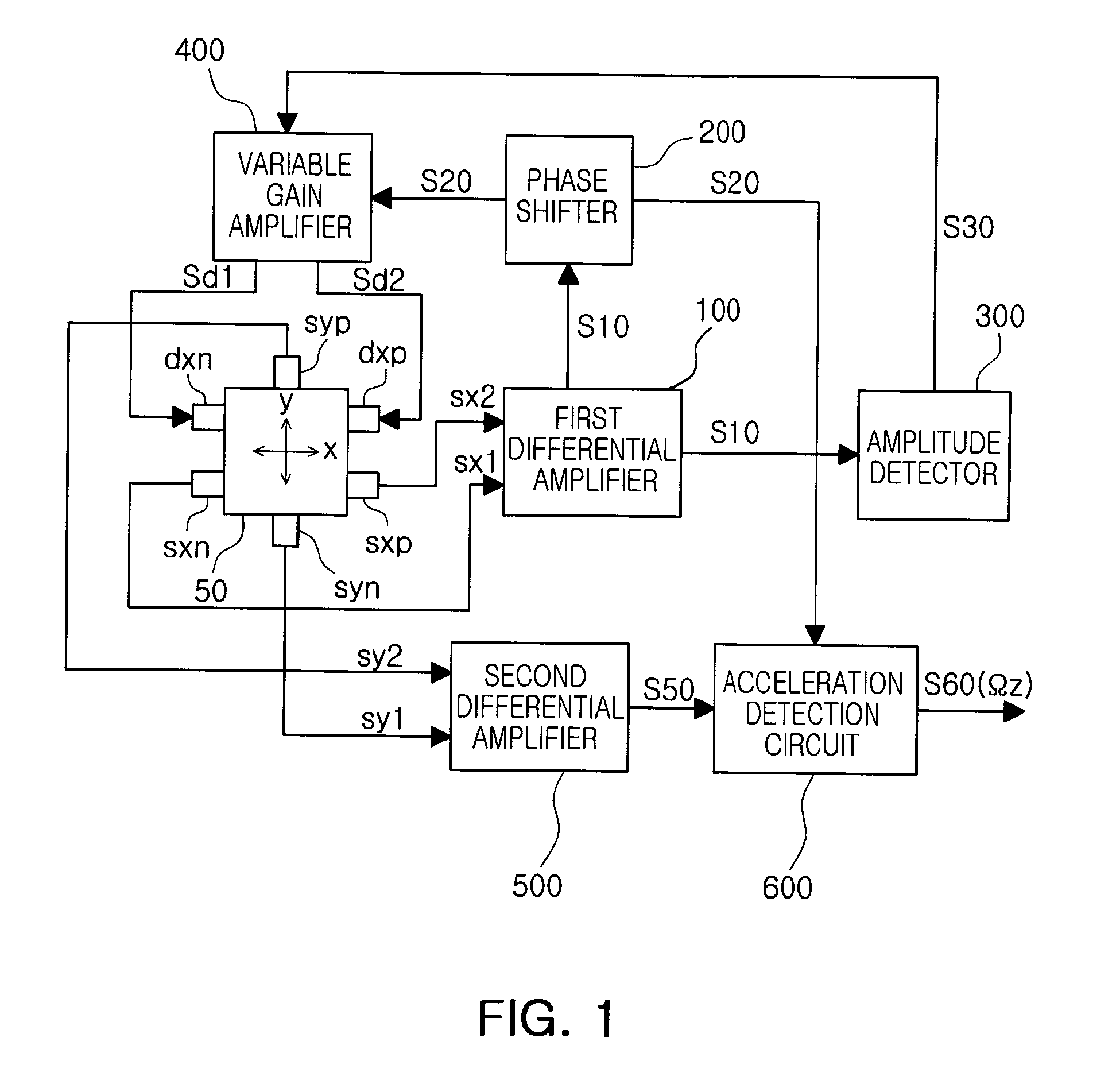
[0025]FIG. 1 is a block diagram of a gyroscope sensor circuit according to an exemplary embodiment of the present invention.

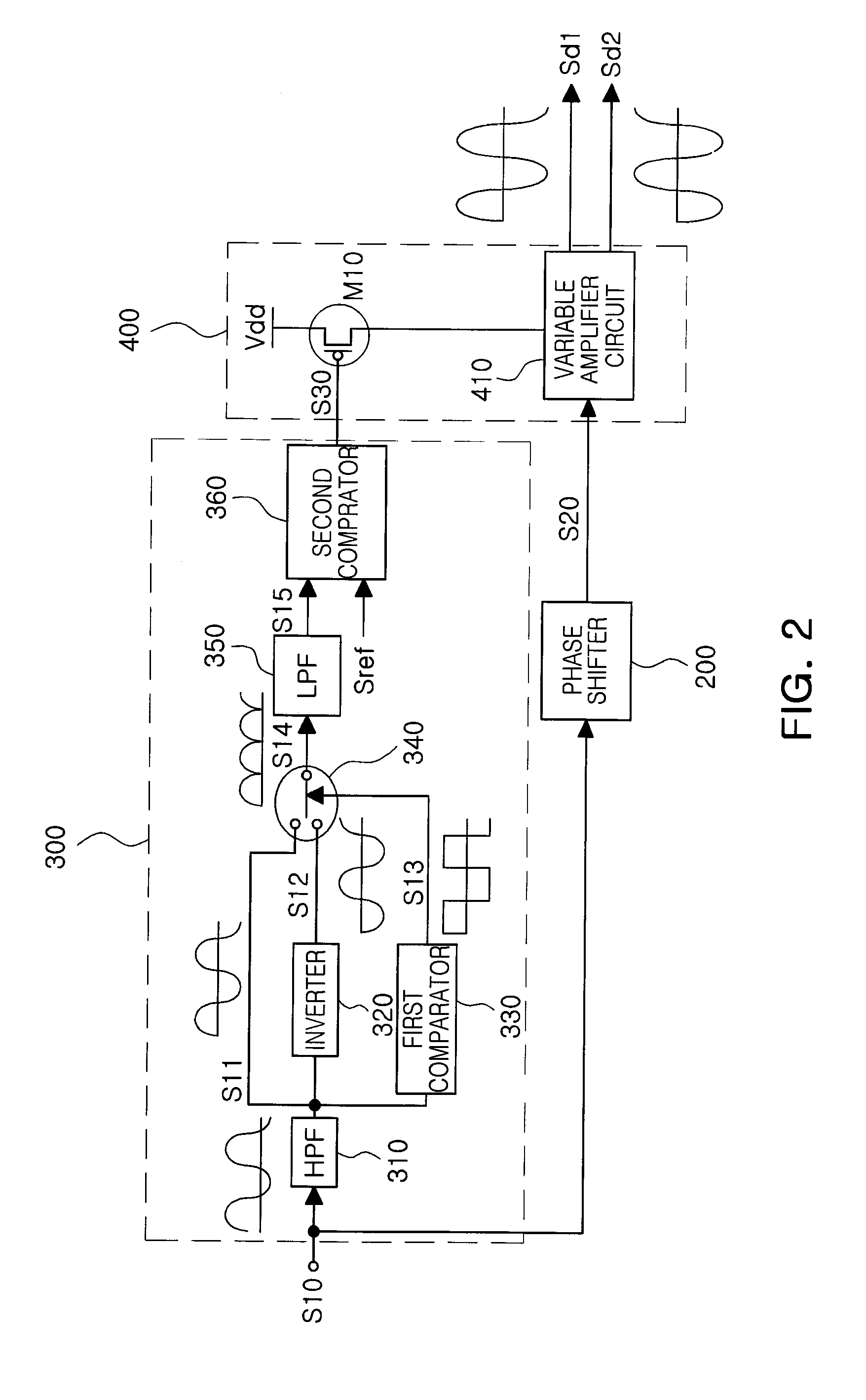
[0026]Referring to FIG. 1, a gyroscope sensor circuit according to an exemplary embodiment of the present invention may include a first differential amplifier 100 differentially amplifying signals outputted from first sensing nodes sxn and sxp of a gyroscope sensor 50; a phase shifter 200 shifting a signal from the first...


PUM


Abstract

Disclosed is a gyroscope sensor circuit, including a first differential amplifier differentially amplifying signals outputted from first sensing nodes of a gyroscope sensor; a phase shifter shifting a signal from the first differential amplifier by a predetermined shift phase; an amplitude detector detecting the amplitude magnitude of the signal from the first differential amplifier; and a variable gain amplifier amplifying the shifted signal from the phase shifter with gain adjusted depending on the amplitude magnitude from the amplitude detector, and providing the amplified signal to driving nodes of the gyroscope sensor.

Description

CROSS-REFERENCE TO RELATED APPLICATIONS[0001]This application claims the priority of Korean Patent Application No. 10-2010-0060218 filed on Jun. 24, 2010, in the Korean Intellectual Property Office, the disclosure of which is incorporated herein by reference.BACKGROUND OF THE INVENTION[0002]1. Field of the Invention[0003]The present invention relates to a gyroscope sensor circuit applicable to mobile terminals such as cameras, cell phones, or the like, and more particularly, to a gyroscope sensor circuit capable of maintaining constant amplitude in a driving signal of a gyroscope sensor, decreasing the influence of temperature, and reducing settling time, by using automatic gain control.[0004]2. Description of the Related Art[0005]In general, a gyroscope sensor (i.e. a gyroscope) may measure an angular velocity Ωz with Coriolis Force (Fy=ΩmzVx) in the state in which a mass body having a certain level of mass m is vibrated at a constant velocity Vx. Here, a velocity Vx should be cons...

Claims


Application Information

Patent Timeline
IPC IPC(8): G01C19/56
CPCG01C19/5776G01C19/5649
Inventor KIM, CHANG HYUN
Owner SAMSUNG ELECTRO MECHANICS CO LTD
Learn More