Lithium ion secondary battery charging method and battery pack
- Summary
- Abstract
- Description
- Claims
- Application Information
AI Technical Summary
Benefits of technology
Problems solved by technology
Method used
Image

Examples
embodiment 1
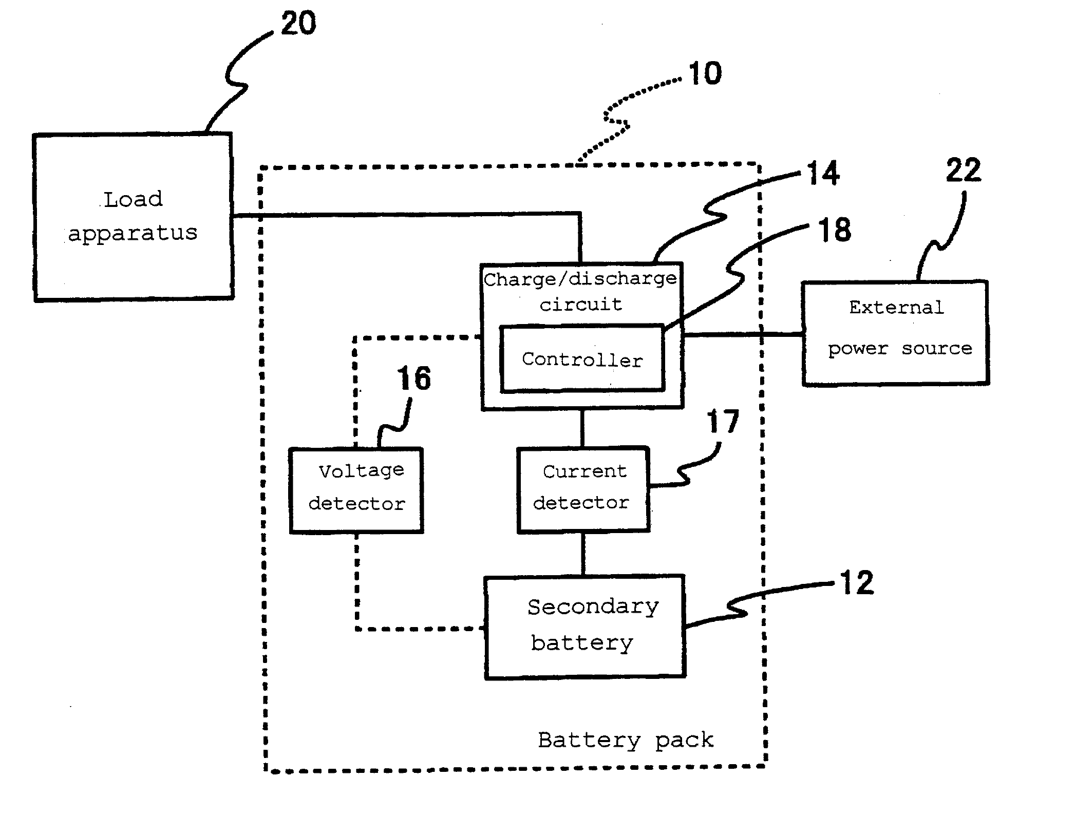
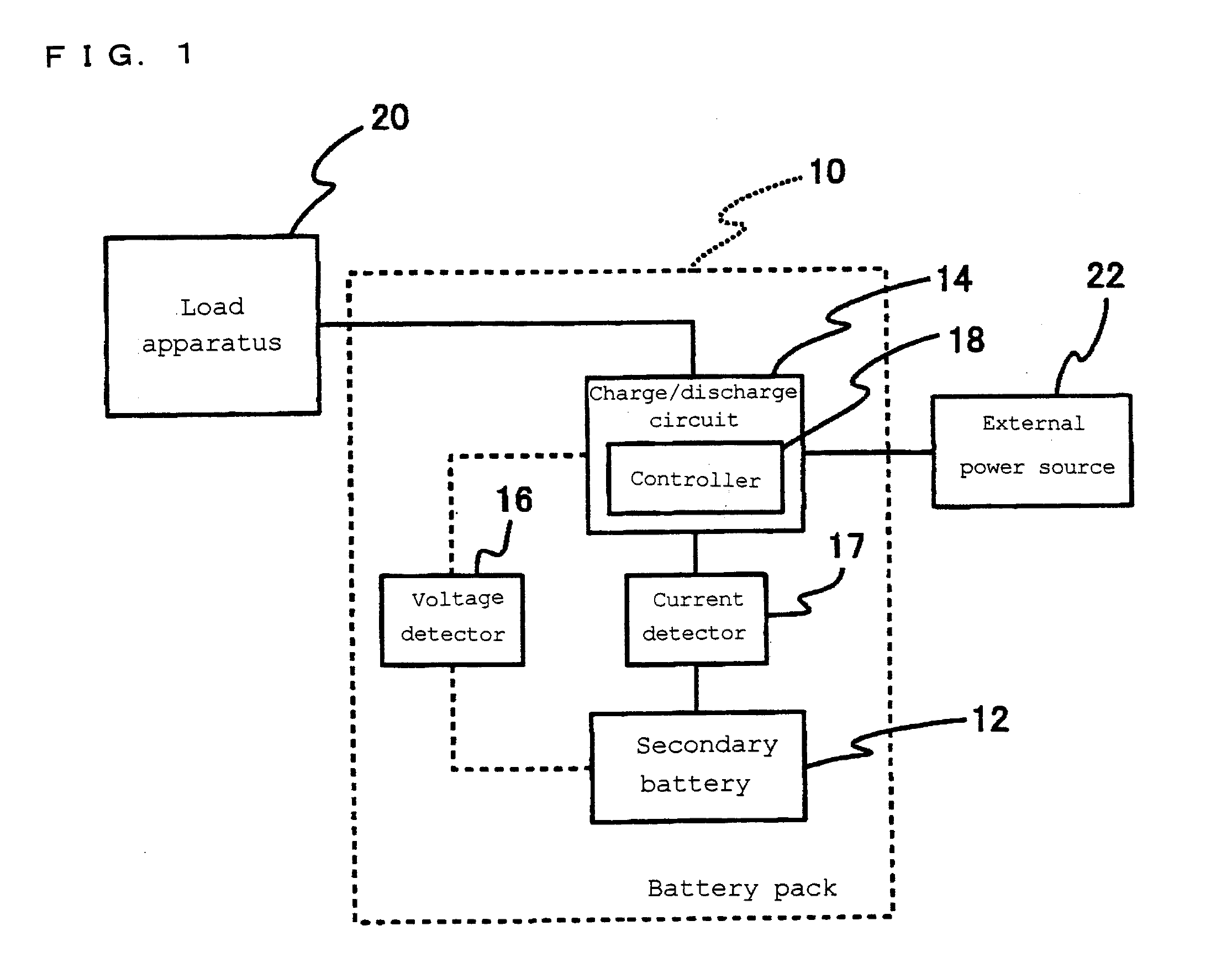
[0078]FIG. 1 is a function block diagram showing a battery pack to which a method for charging a lithium ion secondary battery according to Embodiment 1 of the present invention is applied.
[0079]A battery pack 10 includes a secondary battery 12, a charge / discharge circuit 14, a voltage detector 16 for detecting the voltage of the secondary battery 12, and a current detector 17 for detecting the current of the secondary battery 12. The battery pack 10 is capable of being connected to a load apparatus 20 and an external power source 22.
[0080]The charge / discharge circuit 14 includes a controller 18. The secondary battery 12 in the battery pack 10 may be one lithium ion secondary battery, or alternatively, a battery group comprising a plurality of lithium ion secondary batteries connected to each other in parallel and / or series. The controller 18 may be provided independently from the charge / discharge circuit 14. Some of the below-described controlling functions of the controller 18 may...
example 1
[0131]Among the above-fabricated lithium ion secondary batteries for test use, the one including a sealing plate assembly having an electrical resistance between the bottom plate and the terminal plate of 1 mΩ was used. The lithium ion secondary battery was subjected to constant-current charging at a current of 2 C (Ic(1)) until the charge voltage reached 3.8 V (Ecs(1)) (the first step). After the charge voltage reached 3.8 V, constant-current charging was performed at a charge current of 1 C (Icf) until the charge voltage reached 4.2 V (Ecsf) (the second step). After the charge voltage reached 4.2 V, the battery was subjected to constant-voltage charging at that voltage, with the end-of-charge current set to 50 mA (the third step).
[0132]When the charge current dropped to 50 mA, charging was stopped. Upon passage of 20 minutes thereafter, the battery was discharged at a discharge rate of 1 C, with the end-of-discharge voltage set to 2.5 V. The above charge / discharge process was rega...
example 2
[0133]A total of 300 charge / discharge cycles were performed in the same manner as in Example 1, except that Ecs(1) was set to 4 V in the first step.
PUM
 Abstract
Description
Claims
Application Information
 - R&D Engineer
- R&D Manager
- IP Professional
- Industry Leading Data Capabilities
- Powerful AI technology
- Patent DNA Extraction
Browse by: Latest US Patents, China's latest patents, Technical Efficacy Thesaurus, Application Domain, Technology Topic.
© 2024 PatSnap. All rights reserved.Legal|Privacy policy|Modern Slavery Act Transparency Statement|Sitemap