Braking control system and method for vehicle

Active Publication Date: 2011-12-29
HYUNDAI MOBIS CO LTD
View PDF5 Cites 29 Cited by
  • Summary
  • Abstract
  • Description
  • Claims
  • Application Information

AI Technical Summary

Benefits of technology

[0050]Further, it is possible to reduce the number of electronic control unit equipped with each wheel, s

Problems solved by technology

A hydraulic brake system strongly pushes a pad to a disc in braking, using hydraulic pressure and has a configuration including not only the hydraulic line connected to a master cylinder operated to generate hydraulic pressure by a booster increasing pedal operation force and a wheel cylinder, but various devices controlling and complimenting the cylinders, such that the configuration is correspondingly complicated.
Accordingly, there are some limits in ensuring safety and reliability of braking performance using hydraulic pressure, due to the complicated configuration.
However, in spite of many advantages, the electronic brake system is pointed out that a vehicle with wheels equipped with the electronic brakes has considerably lower safety than a vehicle equipped with

Method used


Image

  • Braking control system and method for vehicle
  • Braking control system and method for vehicle
  • Braking control system and method for vehicle

Examples


Example

First Exemplary Embodiment

[0080]FIG. 4 is a diagram illustrating a first exemplary embodiment of a braking control system for a vehicle which is controlled in the priority order according to the present invention.

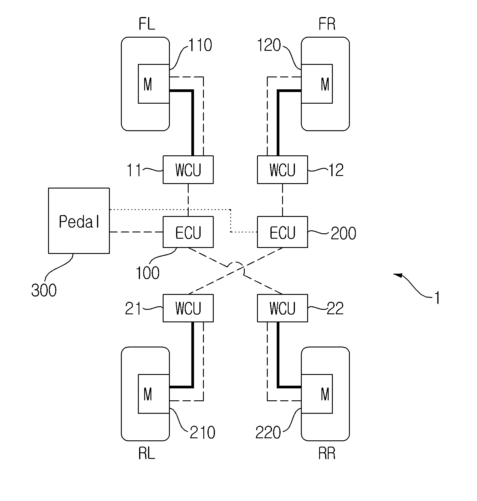
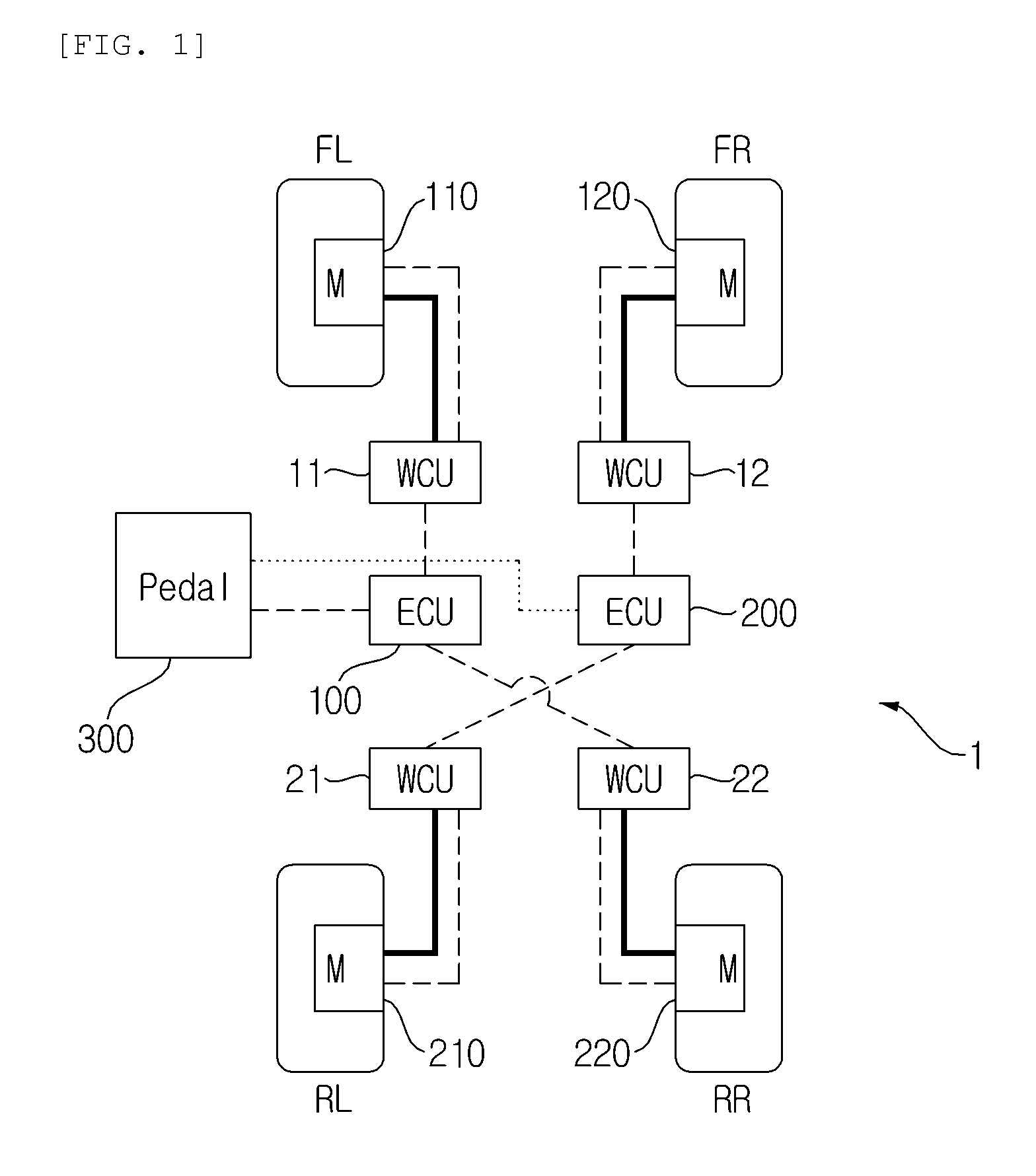
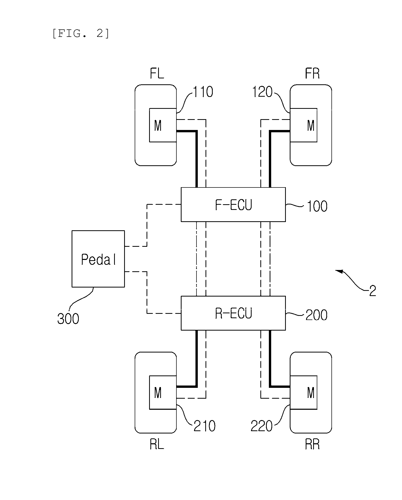
[0081]As shown in FIG. 4, the first exemplary embodiment exemplifies when a fail occurs in the F-ECU 100* and no fail occurs in the first and second electronic brakes. Basically, it is ideal to apply braking force to all of the four wheels to brake a vehicle (normal mode). However, braking should be achieved even if an unexpected fail occurs and the priority order in braking a vehicle traveling forward with two electronic brakes is as follows.

[0082]First Order) Braking with the electronic brakes of the front wheels (first and second electronic brakes).

[0083]Second Order) X-split braking (braking with the first and fourth electronic brakes 110 and 220 or the second and third electronic brake 120 and 210).

[0084]Third Order) Braking with the electronic brakes of the rear wheel...

Example

Second Exemplary Embodiment

[0086]FIG. 5 is a diagram illustrating a second exemplary embodiment of a braking control system for a vehicle which is controlled in the priority order according to the present invention.

[0087]As shown in FIG. 5, the second exemplary embodiment exemplifies when a fail occurs in the F-ECU 100* and the second electronic brake 120*.

[0088]In this case, according to the priority order of braking described above, it is impossible to perform braking by using only the electronic brakes of the front wheels, which corresponds to the first order.

[0089]Therefore, in the case shown in FIG. 5, the first electronic brake 110 at the FL and the fourth electronic brake 220 at the RR are controlled to operate braking by the R-ECU 200. This control follows the predetermined priority order logic programmed in the R-ECU 200.

[0090]Refer to the above description for the details of the predetermined priority order logic. In the second exemplary embodiment, the R-ECU 200 recognize...

Example

Third Exemplary Embodiment

[0091]FIG. 6 is a diagram illustrating a third exemplary embodiment of a braking control system for a vehicle which is controlled in the priority order according to the present invention.

[0092]As shown in FIG. 6, the third exemplary embodiment exemplifies when a fail occurs in the R-ECU 220* and the first and second electronic brakes 110* and 120*.

[0093]In this case, according to the priority order of braking described above, it is impossible to perform braking according to both of the first and second orders.

[0094]Therefore, in the case shown in FIG. 6, the third electronic brake 210 at the RL and the fourth electronic brake 220 at the RR are controlled to operate braking by the F-ECU 100. This control follows the predetermined priority order logic programmed in the F-ECU 100.

[0095]Refer to the above description for the details of the predetermined priority order logic. In the third exemplary embodiment, the F-ECU 100 recognizes that a fail occurs in the R...


PUM


Abstract

Provided are a braking control system for a vehicle which is controlled in a priority order, and a method of the same. In more detail, the present invention relates to a braking control system for a vehicle equipped with an electronic brake at each wheel, in which the braking control system includes: a first control unit controlling the operation of a first electronic brake mounted at a front-left wheel and a second electronic brake mounted at a front-right wheel in response to braking signals; and a second control unit controlling the operation of a third electronic brake mounted at a rear-left wheel and a fourth electronic brake mounted at a rear-right wheel in response to the braking signals. In this configuration, when a fail occurs in any one of the first and second control units, the other control unit selectively controls at least one or more of the first to fourth electronic brakes, in accordance with predetermined logic.

Description

BACKGROUND OF THE INVENTION[0001]1. Field of the Invention[0002]The present invention relates to a brake system of a brake-by-wire type vehicle, and more particularly, to technology of adaptively braking a vehicle in response to fails in a control unit or fails in electronic brakes respectively installed at the wheels, in a brake system that includes the electronic brakes installed at the wheels and achieves braking by an electronic control unit.[0003]Further, the present invention relates to a technology of preparing for fails in the brake system of brake-by-wire type vehicles, that is, a fail-safe technology of a brake system.[0004]2. Description of the Related Art[0005]In general, the brake-by-wire is a kind of new technology used for vehicles in recent years, which has been developed to remove several parts and simplify assembly by using electronic control called ‘by-wire’. That is, it is a concept used for controlling braking force by using electronic signals, replacing hydraul...

Claims


Application Information

Patent Timeline
IPC IPC(8): B60T13/74G06F19/00
CPCB60T8/885B60T13/741B60T2270/413B60T17/22B60T2270/404B60T13/746
Inventor KIM, JONG SUNG
Owner HYUNDAI MOBIS CO LTD
Why Eureka
Try Eureka