
Information processing apparatus, power source control method of information processing apparatus, program of power source control method, and storage of program

Inactive Publication Date: 2011-12-29
RICOH KK
View PDF4 Cites 7 Cited by
  • Summary
  • Abstract
  • Description
  • Claims
  • Application Information

AI Technical Summary

Benefits of technology

a discharge controller to control a discharge speed of the auxiliary power source. When a voltage output of the main power source becomes a preset reference voltage value, the discharge controller switches a power source for supplying power to the information writing processor from the main power source to the auxiliary power source,

Problems solved by technology

However, there is an upper limit to the number of times the memory can be rewritten, because memory elements in non-volatile memories used for IC tags deteriorate by repeating the refreshing process.
However, such integrated circuits generally have an upper limit for fall time of the power voltage supplied to the ICs when the power OFF state is set for the image forming apparatus.
As such, although the ICs may be configured to be operated properly when the power voltage supplied to the ICs decreases to a given value within the upper limit for the fall time of the power voltage, if the actual fall time of the power voltage of the ICs exceeds the upper limit of the fall time, the IC tags using such ICs may malfunction.

Method used


Image

  • Information processing apparatus, power source control method of information processing apparatus, program of power source control method, and storage of program
  • Information processing apparatus, power source control method of information processing apparatus, program of power source control method, and storage of program
  • Information processing apparatus, power source control method of information processing apparatus, program of power source control method, and storage of program

Examples


first example embodiment

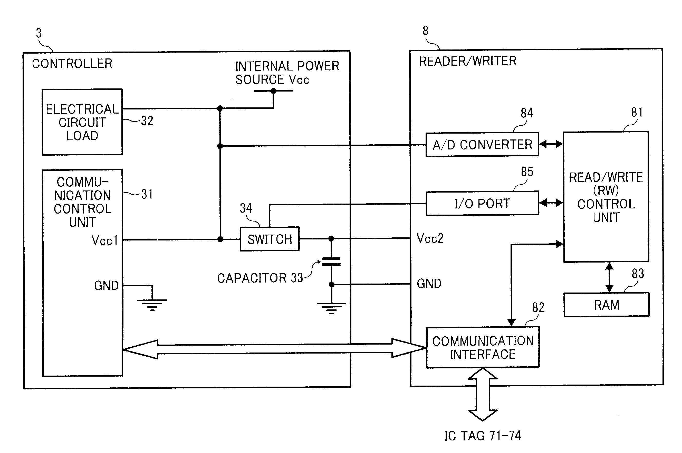
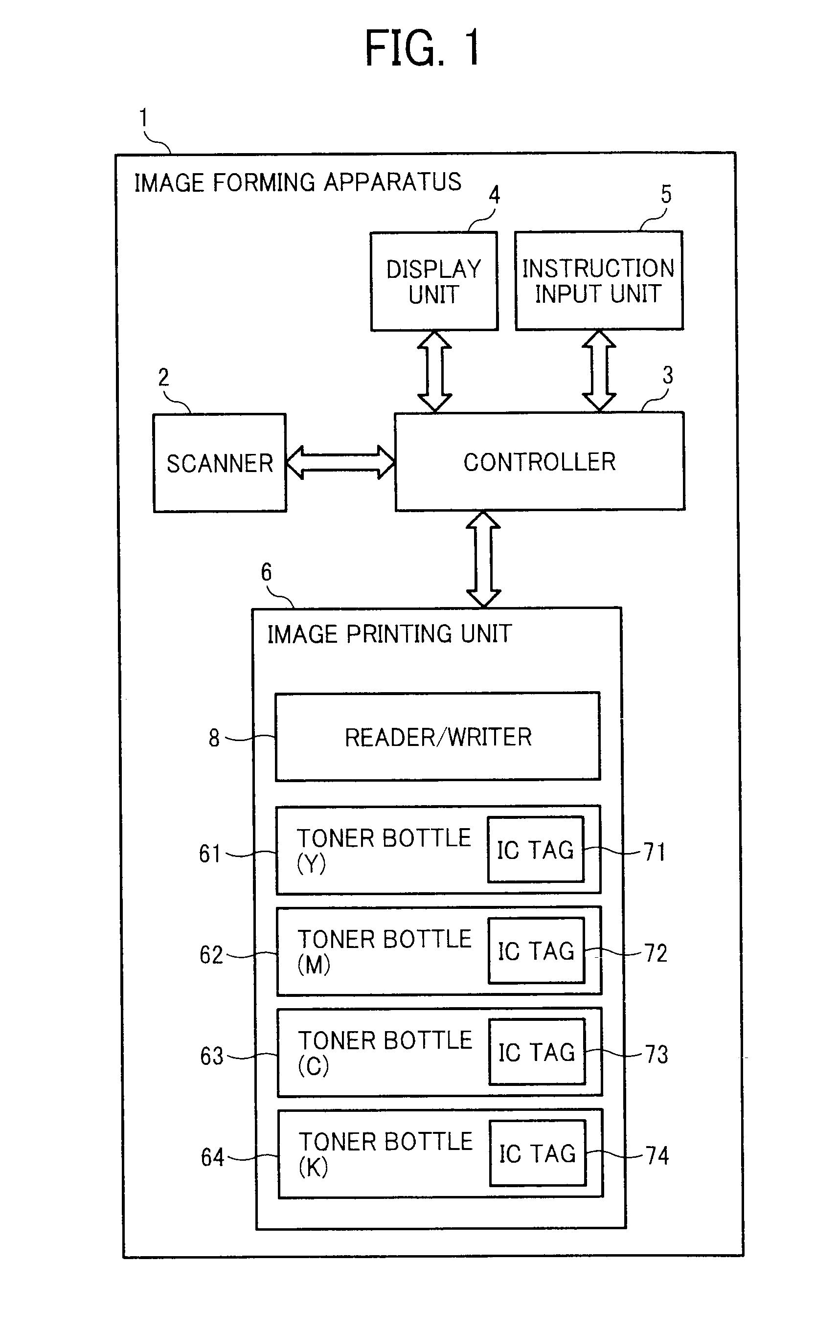
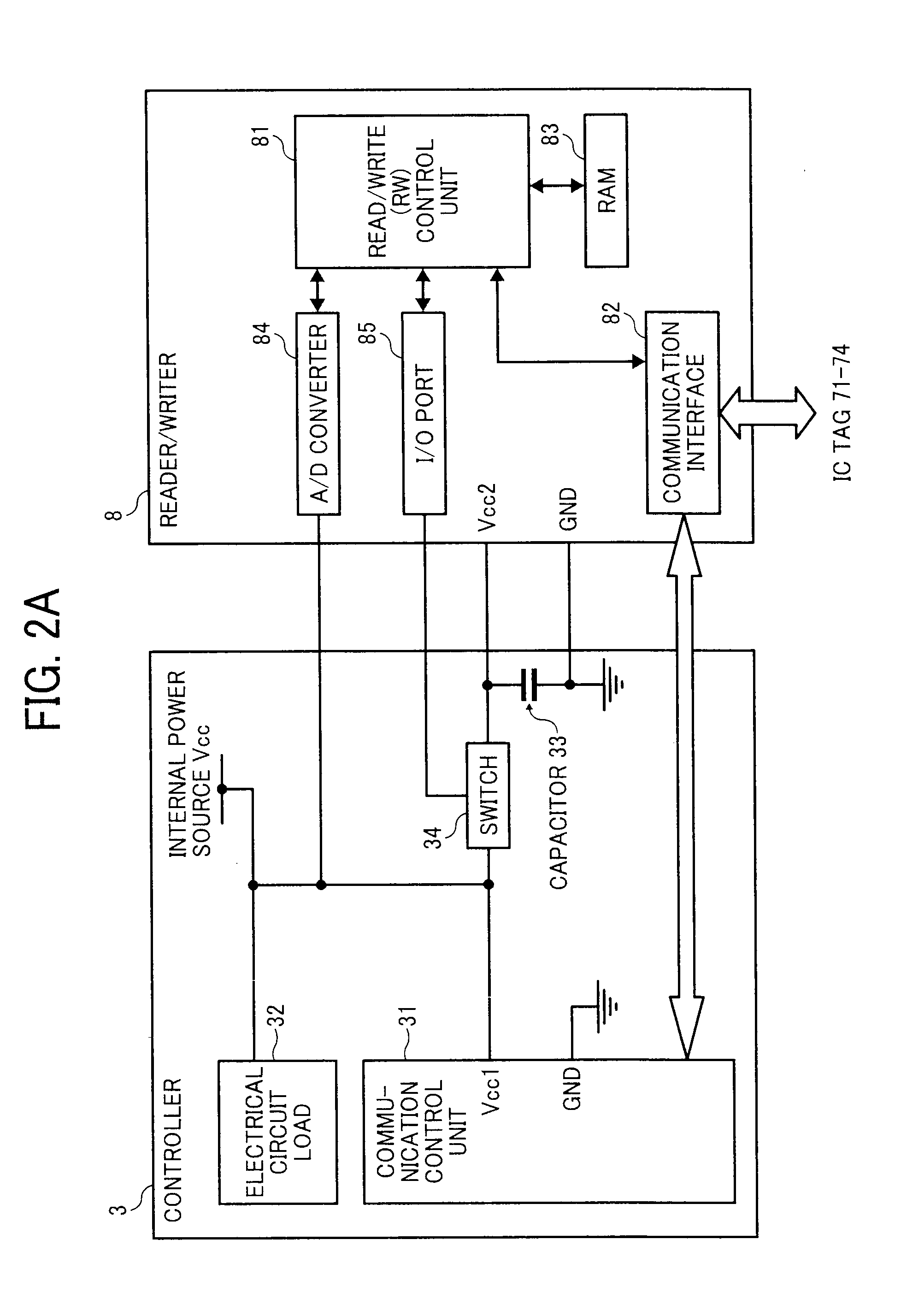
FIG. 1 shows an example block diagram of an image forming apparatus 1 according to a first example embodiment, in which the image forming apparatus 1 is described as one example of information processing apparatuses. Hereinafter, information or data processing for the image forming apparatus 1 is described. However, it should be noted that the following example embodiments for processing information or data can be applied to various types of information processing apparatuses, not limited to the image forming apparatuses such as printers, copiers, etc. The image forming apparatus 1 may include a scanner 2, a controller 3, a display unit 4, an instruction input unit 5, and an image printing unit 6.

The scanner 2 scans document image, and converts image to electrical signals to output and image data. As such, the scanner 2 is used as an image scanning unit. The controller 3 processes the image data output from the scanner 2, and controls each unit in the image forming apparatus 1. The ...

second example embodiment

A description is now given of the image forming apparatus 1 according to a second example embodiment. The image forming apparatus 1 according to the second example embodiment may use a reset integrated circuit (IC) 88 as shown in FIG. 2B instead of the A / D converter 84 used in the image forming apparatus 1 of the first example embodiment. For example, the reset IC can output a high voltage when the voltage value of a power source is at a given value or more, or output a low voltage when the voltage value of a power source falls below a given value. Such output signal from the reset IC 88 can be used as an interruption signal of the RW control unit 81 to detect a decrease of the internal power source Vcc.

In the second example embodiment, the RW control unit 81 does not need to read the voltage value data from the A / D converter 84, and does not need to compare the read voltage value and the reference voltage value, by which the voltage decrease of power source can be detected promptly...

third example embodiment

A description is now given of an image forming apparatus according to a third example embodiment. As for the image forming apparatus 1 according to the first example embodiment, when the RW control unit 81 returns the first switch 34 at the ON state at step S110 in FIG. 3, the terminal voltage of the capacitor 33 may be applied to the power terminal Vcc1 of the communication control unit 31. In the third example embodiment, another switch is further disposed between the power terminal Vcc1 and the capacitor 33 to prevent such application of the terminal voltage of the capacitor 33 to the power terminal Vcc1 of the communication control unit 31.

In the first example embodiment, when the first switch 34 is returned to the ON state at step S110 (FIG. 3), the voltage applied to the power terminal Vcc1 of communication control unit 31 may become a same voltage applied to the power terminal Vcc2 of the reader / writer 8. Therefore, from the time t3 to t4 shown in FIG. 4, the voltage applied ...


PUM


Abstract

An information processing apparatus includes an information storage to store information indicating a state of the information processing apparatus; an information writing processor to write the information to the information storage; a main power source and an auxiliary power source to supply power to the information writing processor; and a discharge controller to control a discharge speed of the auxiliary power source. When a voltage output of the main power source becomes a reference voltage, the discharge controller switches a power source for the information writing processor from the main power source to the auxiliary power source, and then after completing information writing to the information storage by using the information writing processor and the auxiliary power source, the discharge controller controls the discharge speed of the auxiliary power source to decrease a voltage output of the auxiliary power source to a given voltage within a given time period.

Description

CROSS-REFERENCE TO RELATED APPLICATIONSThis application claims priority to Japanese Patent Application No. 2010-146116, filed on Jun. 28, 2010 in the Japan Patent Office, which is incorporated by reference herein in its entirety.BACKGROUND OF THE INVENTION1. Field of the InventionThe present invention relates to an information processing such as image forming apparatus having a data writing function to a non-volatile memory such as an integrated circuit (IC) tag, and a method of controlling a power source of the information processing apparatus.2. Description of the Background ArtInformation processing apparatuses such as image forming apparatuses have been equipped with enhanced machine information service for maintenance service of machines and / or enhanced information providing service to machine users, by which service engineers and / or users can obtain and utilize settings information related to machines and / or use-state information of consumables. Such information can be obtaine...

Claims


Application Information

Patent Timeline
IPC IPC(8): G06F1/26G06F12/00
CPCG06K7/10207G06F1/30
Inventor INOKUCHI, SUMIHIROYAMAMOTO, MITSUFUMIOKAMURA, SHUGOAOKI, TOYOKAZUKAWAMURA, TAKUMIYAMANOBE, KOUJIMURAISHI, NORIOSATO, KAZUYUKI
Owner RICOH KK
Learn More