

Low loss shunt regulator
a shunt regulator and low loss technology, applied in the direction of electric generator control, dynamo-electric converter control, transportation and packaging, etc., can solve the problems of reducing power at low and high engine speed, charging system to compromise between power, and increasing cost, so as to achieve low voltage output and generate more power.
- Summary
- Abstract
- Description
- Claims
- Application Information
AI Technical Summary
Benefits of technology
Problems solved by technology
Method used
Image

Examples
Embodiment Construction
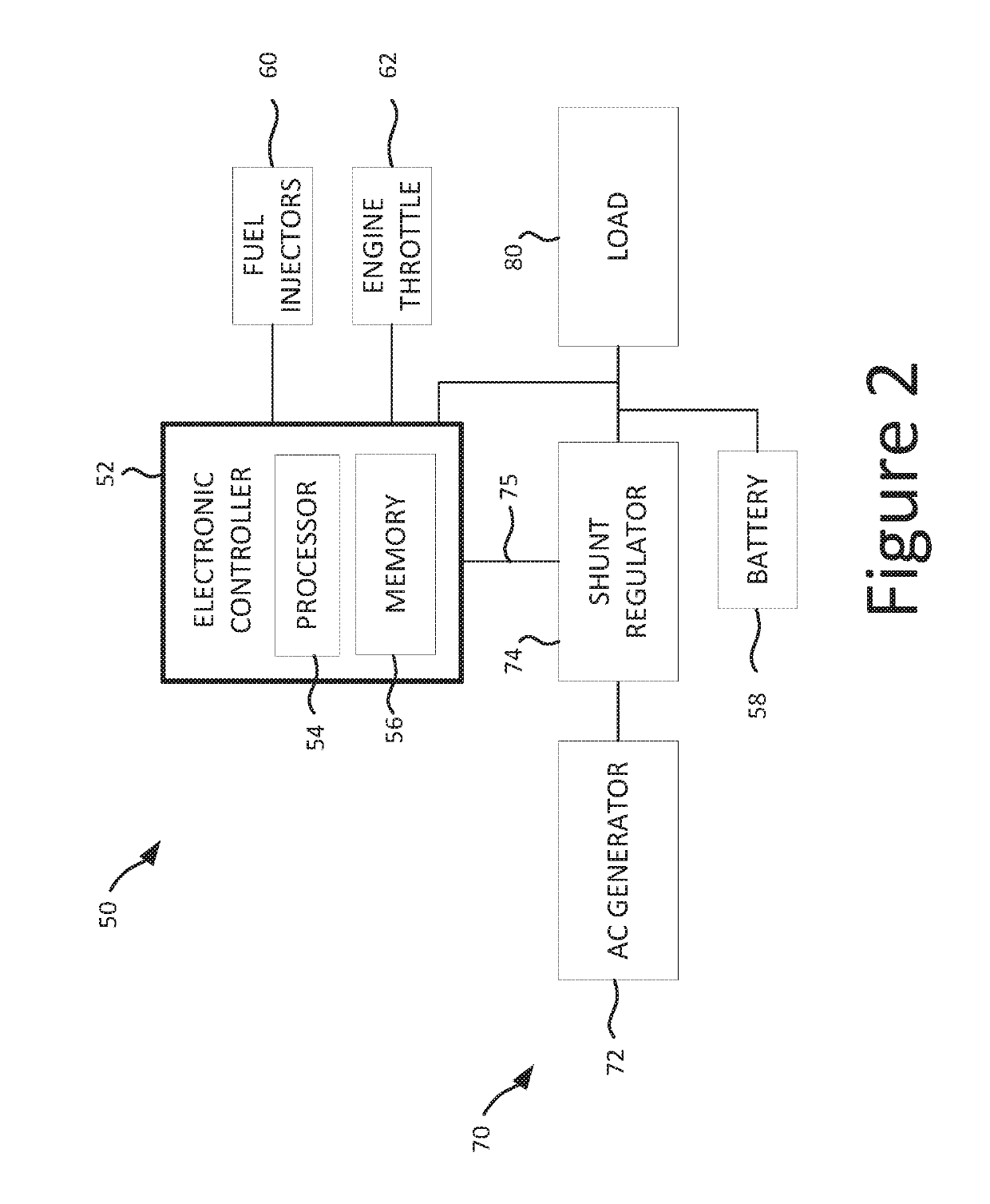
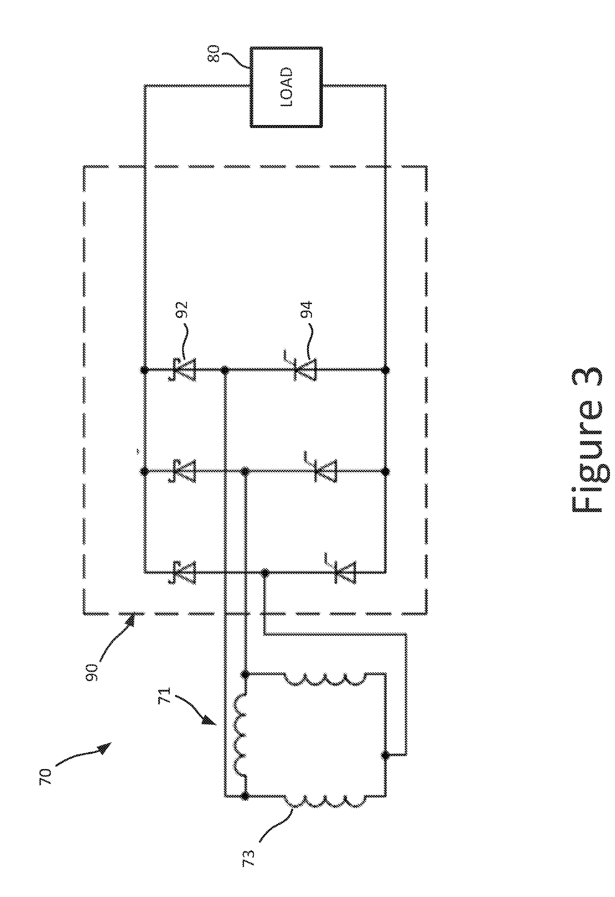
[0007]The present disclosure provides a shunt regulator operative to harvest larger amounts of power from an alternating-current (AC) generator than conventional regulators. In some embodiments, the AC generator has fewer windings than a conventional generator and thereby produces a lower voltage output, which in combination with the novel shunt regulator enables the power generation system to generate more power at low and high revolutions per minute of the engine. In one example, the nominal rectified voltage of the AC generator is about 50% less than the direct-current (DC) buss voltage of the vehicle. Accordingly, the low voltage is boosted by the shunt regulator to generate the DC bus voltage.
[0008]In some embodiments, the shunt regulator utilizes low loss field effect transistors (FETs) to implement switching transformations more efficiently than conventional regulators, permitting construction of a regulator in which the power switches are not potted.
[0009]In some embodiments...
PUM
 Abstract
Description
Claims
Application Information